background image

P. 10


Installation 

Guide

 CT-3200


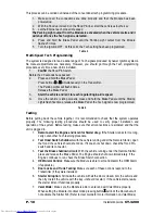
This process can be carried out instead of the conventional tach programming procedure.  

1.


Make sure all the connections are done properly and that the Module has been 
powered-up. 

2.


With the Hood up (Ground on the Hood Pin line), start the vehicle using the key. 

3.


Let the Engine reach proper idle speed 

The Parking Light output from the Module is activated when the vehicle starts and it 
will shut off once the Tach signal is detected. 

4.


Press and hold the Brake Pedal until the Parking Light output from the Module 
flashes 5 times.  

5.


Turn the Ignition OFF.  At this point, the Tach setting has been programmed. 

Table 4 

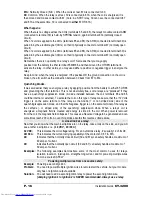
Multi-Speed Tach Programming  

The system is designed to read a wide range of Tach signals produced by newer Ignition systems. 
No manual adjustments are necessary. However, you should go through the Tach programming 
procedure every time a new Unit is installed. 

1.


FLASH 

the Hood Pin Switch.


Before the 20 seconds have passed.


2.


Press and hold the Brake Pedal.


Press buttons 

Ι

 & 

ΙΙ

 simultaneously on the Transmitter. 

The Parking Lights will flash 4 times. 
Release the Brake Pedal. 

3.


Start the vehicle and let it to reach regular Engine-idle speed. 

4. 

Once the vehicle is idling properly, press and hold the Brake Pedal until the Parking 
Lights flash five times, release the Brake Pedal: the Tach signal is now programmed.


Table 5 

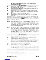
Testing 

Before putting back the vehicle together, it is recommended to check that the system operates 
properly. The following testing procedures should be used to verify proper installation and 
operation of the system. Before testing, make sure that all connections are soldered and that the 
unit is plugged in. 

1.


Remote-start the Engine and listen for Starter drag. 

If the Starter cranks for too long, 

carry out another Tach learning procedure. 

2.


Test Hood Switch shutdown

: with the vehicle running under the Remote Starter, open 

the Hood; the vehicle should shut down. If it does not shut down, check the Hood Pin-
switch and its connector. 

3.


Test the Brake shutdown circuit

: With the vehicle running under the Remote Starter, 

press and release the Brake Pedal. The Engine should shut down immediately. If the 
Engine continues to run, check the Brake Switch connection. 

4.


OEM Alarm Control:

 Make sure the Module is able to arm and disarm the OEM Alarm 

(if applicable). 

5.


Door Locks and Trunk Testing: 

Make sure each of these options respond to the 

Transmitter (if they were installed). 

6.


Starter Kill option:

 Sit inside the vehicle with all the Doors closed. Arm the vehicle and 

then try to start the vehicle with the key –it should not start.  If the vehicle starts, rewire 
the starter kill so it functions properly. 

7.


Valet Mode:


Make sure the Module is able to enter and exit Valet Mode properly. 

When setting the Module into Valet mode pressing button 

Ι

 will lock the Doors but will 

not activate the Starter Kill.


(Refer to User Guide for more information on Valet Mode) 

Downloaded from 

www.Manualslib.com


manuals search engine


Содержание CT-3100

Страница 1: ...U T O M A T I C T R A N S M I S S I O N M U L T I C H A N N E L R E M O T E S T A R T E R S Y S T E M CT 3200 Installation Guide Table of Contents Introduction 2 Included in the Package 2 Installation...

Страница 2: ...device To reduce potential radio interference to other users the antenna type and its gain should be so chosen that the equivalent isotropically radiated power EIRP is not more than that required for...

Страница 3: ...to the remote starter module are properly fused and diode isolated when testing the shock sensor never test on glass with an opened hand and never hit glass hard enough as to break it When testing on...

Страница 4: ...or starter wires must use external relays DO NOT JUMP WIRES at the ignition switch this will compromise the OEM electrical system 5 Pin Secondary Harness Wire Description 1 BLACK Chassis ground input...

Страница 5: ...7 WHITE ORANGE Starter Kill Armed output The unit is equipped with a selectable passive or active arming starter kill circuit that will immobilize the vehicle when the system is armed This wire will p...

Страница 6: ...onnected to the ground out wire ensure that they are all diode isolated in order to avoid feedback and damaging the vehicle 11 GREY N A This pin is not used leave empty 12 YELLOW Glow plug input This...

Страница 7: ...programming centre Once the module is in the programming centre the installer has no more than 20 seconds to get into one of the sub menus Failure to do so will result in the module exiting the progra...

Страница 8: ...ion mode the parking lights will flash once twice depending on the option you have entered The unit will stay in programming mode until the hood pin switch or the brake pedal is pressed again therefor...

Страница 9: ...ion should be selected ONLY if the starter kill is installed MODE 2 indicates default setting FUNCTION 1 Engine Run Time OPTION 1 4 minute Run Time in Gas Mode 9 minute in Diesel Mode OPTION 2 15 minu...

Страница 10: ...back the vehicle together it is recommended to check that the system operates properly The following testing procedures should be used to verify proper installation and operation of the system Before...

Страница 11: ...h set of ote Only one set of pins can be used at a time ote Only one set of pins can be used at a time pins has a function To activate one of the three possible 2nd outputs place the Jumper supplied o...

Страница 12: ...lse dur default 4 sec LOCK and UNLOCK pulses or for a 7 10 sec LOCK pulse and two 1 4 second UNLOCK pulses used for double pulse disarm unlock systems In GAS mode the Mod minutes In DIESEL mode the Mo...

Страница 13: ...metal in the car The shape of the po ge 13 The shape of the roof and A pillars brings about considerable radio frequency deflection in this case th fa relation to the remote control can affect the ran...

Страница 14: ...drill a hole through the fire wall This will protect the wires from rubbing against the bare metal and possibly shorting out If you are installing an Alarm starter combo module mount the siren in the...

Страница 15: ...cle can be put back together A basic introduction to the Relay What is a relay A device that responds to a small current or voltage change by activating switches or other devices in an electric circui...

Страница 16: ...een the coil terminals 85 and 86 could be internal or external To activate the coil on this type of relay make sure that the 12 Volts trigger is on the same terminal of the relay as the Anode or non s...

Страница 17: ...ctivates the wipers Where the connection was made from the start modules Park light output and the vehicle s park light circuit the OEM park light wire is cut to isolate the park light switch and the...

Страница 18: ...cut The side of the wire that is still connected to the Ignition switch becomes the Key Side of the starter wire The side of the wire that is still connected to the starter motor becomes the Starter S...

Страница 19: ...trol can affect the range Straight on standing in front of the vehicle generally gives you the greatest range the second best performance is from the back Using the remote control from either side of...

Страница 20: ...Weak Tach signal Bad ground 7 The car starts by remote but then the starter re engages Check ground wire Is Tach programmed 8 The car starts on it s own Is the module in cold weather mode Program remo...

Страница 21: ...hicle have factory alarm keyless entry You might have to switch to a 433MHZ module Some GM Trucks Cavalier Sunfire Breeze Stratus Cirrus 22 Sometimes I have to press button I twice to lock my doors No...

Отзывы: