MVI56-DEM
♦
ControlLogix Platform
Reference
Honeywell DE Communication Module
Page 62 of 80
ProSoft Technology, Inc.
March 6, 2008
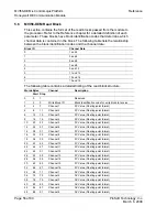
Words Bytes
Start
Stop
Channel Description
120
240
243
Eighth Channel
LRV=(LRV/URL) (Float format)
122
244
247
URV=((URV-LRV)/URL) (Float format)
124
248
251
URL (Float format)
126
252
255
Damping (Float format)
128 256
257
Command
Bits
129 258
259
Function
130
260
DE Configuration
261
Damping
131
262
PV Characterization
263
Sensor Type
132
264
PV Number
265
Number of PV's
133 266
273
Tag
Name
137 274
495 N/A
Spare
5.8
DE Parameter Descriptions
This section contains a detailed listing of the Honeywell DE parameters.
5.8.1 Device Status Flags #1
Bit Name
Description
0
Function Done
0 = Not complete, 1 = Complete
Status Flag associated with the function parameter. When the
Function parameter is set to one(1) to initiate a database write to the
instrument, this bit may be monitored to determine completion
1
Function Passed
0 = Function Failed, 1 = Function Passed
Flag to be used in conjunction with Function Done Flag. When the
Function Command is set to anything besides Imaging PV, the
Function Done Flag is set False, When the requested Function
Command is completed, the MVI will return to the Imaging PV mode,
set the Function Done Flag to 1 and set the Function Passed
depending on the outcome of the command.
Note that if a Download to an Instrument is initiated and no
parameters have been changed in the database, the Function
Passed Flag will
not
be set.
2
PV Update Flag
(Toggles)
This flag indicates that the DEM has received a new PV value from
the instrument in this DE Channel. This flag will be toggled during
the next Block Transfer with the current block read number, unless a
new PV value is received again.
3 PV
Output
This flag indicates that the PV is in Output Mode. In this
implementation the instrument can only be placed in Output Mode by
the SFC (hand held) In this mode, the PV is forced to a value which
overrides the transmitter PV. This is a read only value

