


MVI56-DEM
♦
ControlLogix Platform
Reference
Honeywell DE Communication Module
Page 48 of 80
ProSoft Technology, Inc.
March 6, 2008
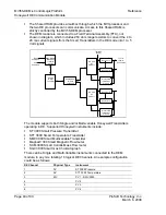
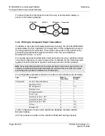
The flow of data from the instrument all of the way to the Operator display is
shown in the following diagram:
SCAN 3000
A-B PLC
DE Module
Transmitter
Read/Write Database
Read Database
Display
Data
Read Only Data
Receive PV
Read Data with Calculated Mismatch
Smart
Transmitter
Receive Data
Base &
Calculate
Mismatch
5.2.4 Writing to Honeywell Smart Transmitters
In addition to the read functionality described previously, the ProSoft MVI56-DEM
module allows the PLC application to change some of the configuration values in
the Honeywell Smart Transmitter. These values are written to the instrument by
pre-loading the appropriate register locations in the PLC and initiating a
Download (Function = 1) cycle.
The module executes the Download Command and returns the completion status
in the Device Status word. Upon receipt of the completion bit, the Download write
register should be cleared to prevent continuous execution of the operation.
Note: The example ladder provided with the module and listed in this document performs the logic
necessary to implement the Download functionality. We recommend the use of this logic, at least
as a starting point, with simple modifications to the addressing.
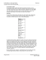
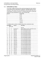
The configuration parameters that can be written to the instrument are as follows:
Type Description
Write to
Transmitter
Mismatch
Tested
Configuration Function:
Download/Upload
N
N
Tag Name: ASCII
Y
Y
DE Configuration
Y
Y(1)
Damping
Value
Y
Y
PV
Characterization
Y
Y
Sensor
Type
Y
Y
Upper Range Value: URV
Y
Y
Lower Range Value: LRV
Y
Y
Upper Range Limit: URL
N
Y(2)
PV Num -
N
Y(2)
Number of PV
N
Y(2)
(1) DE Configuration modes which disable the database read also disable
Mismatch testing
(2) These values are written to the module for Mismatch testing purposes


