Promise Vess A2600 Скачать руководство пользователя страница 34

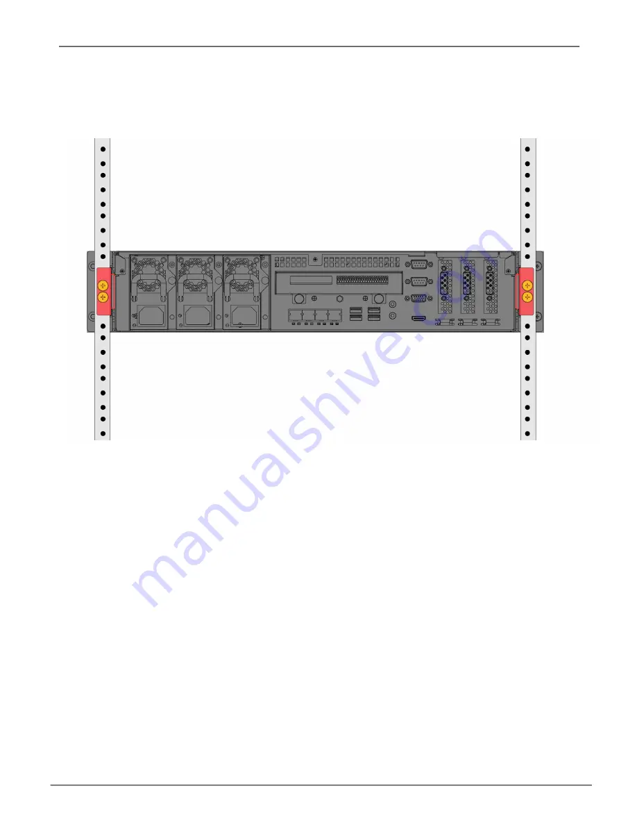
System installed in rack viewed from rear

4.  Secure the enclosure to the rack.

•  The unit attaches to the rack posts using the included screws and flange nuts. 

•  Use the attaching screws and flange nuts that came with the Vess A2200/A2200s enclosure.

28

Vess A2000 Series NVR Storage Appliance   


         Promise Technologies 

Содержание Vess A2600

Страница 1: ...Vess A Series NVR Storage Appliance Product Manual Version 1 2 2015 PROMISE Technology Inc All Rights Reserved...

Страница 2: ...nce in which case the user may be required to take adequate measures Warning The electronic components within the Vess enclosure are sensitive to damage from Electro Static Discharge ESD Observe appro...

Страница 3: ...hysical injury and how to avoid them Caution A Caution informs you of possible equipment damage or loss of data and how to avoid them Important An Important message calls attention to an essential ste...

Страница 4: ...face 63 Choosing a Display Language 65 Subsystem Management 68 Background Activities 69 Manage Background Activities Settings 70 Media Patrol 75 Managing Activity Schedules 76 Event Logs 77 Administra...

Страница 5: ...y Information CLU 135 Enabling Media Patrol PDM and Power Management on a Disk Array CLU 136 Rebuilding a Disk Array CLU 137 Running Media Patrol on a Disk Array CLU 137 Running PDM on a Disk Array CL...

Страница 6: ...Contacting Technical Support 249 Limited Warranty 253 Appendix Driver Installation and Update 257 Update Installation Requirements 258 Update Install the Driver 259 Uninstall Driver 265 How to check...

Страница 7: ...r Linux operating systems a Video Management Software suite and disk drives in order to streamline the installation and integration process The Vess A Class Series subsystems are stand alone devices w...

Страница 8: ...r Windows Embedded Standard 7 Runtime WS7P or Linux CentOS 6 3 operating systems depending on customer preference Management Interfaces Browser based management with WebPAM PROe Command Line Interface...

Страница 9: ...system 32 array 256 system 32 array Hot swap drives Yes Yes Controller Single Single Graphics Ivy Bridge Intel HD Graphics 4000 Ivy Bridge Intel HD Graphics P4000 Memory 8GB DDR up to 16 GB 8GB DDR u...

Страница 10: ...the drive carriers from being unintentionally removed For all Vess Class A Series enclosures defective drives can be replaced without interruption of data availability to the host computer If so confi...

Страница 11: ...equipment rack The system power button and two USB ports are located on the left side and most of the front LED indicators are located on the right side Vess A2600s A2600 front view Drive carriers Pow...

Страница 12: ...s Each drive carrier has two LEDs on the right side of the front the Drive Status LED lo cated above the Activity LED The Drive Status LED displays GREEN when a drive is configured and working properl...

Страница 13: ...RAID Status Lights GREEN when healthy or RED if any RAID volume is offline ORANGE for critical state of any logical drive Global HDD Activity Blinks BLUE to indicate one or more drives are being acce...

Страница 14: ...it to lock or unlock this cover to access the six hard drive carrier trays and removable cooling unit in front The left panel contains the power button various LEDs USB ports and the tubular lock Powe...

Страница 15: ...ealthy RED if the RAID member is offline or there is a physical disk error ORANGE indicates the drive is rebuild ing and a dark LED indicates either no drive is installed or the drive is not configure...

Страница 16: ...ies PSU while the Vess A2600s enclosure is equipped with a single PSU that is not hot swappable Both enclosures are available with the alarm RS 422 and audio RS 485 I O terminal block connection optio...

Страница 17: ...rs on control panel System fan Raiser card slots PSU fan Power switch pictured in ON position Power insert Ports and LED indicators on control panel System fan Raiser card slots Vess A2600s with optio...

Страница 18: ...600 with optional sensor alarm IO ports rear view PSU fans Power inserts Ports and LED indicators on control panel System fan Raiser card slots 12 Vess A2000 Series NVR Storage Appliance Promise Techn...

Страница 19: ...remains dark no connection has been estab lished The LED on the lower right of each port indicates connection speed GREEN is 100 Mbps ORANGE is 1000 Mbps PSU Vess A2600 The power supply LEDs on the A...

Страница 20: ...e RS 232 Port 1 This is used for control line connection to an uninterruptible power supply UPS RS 232 Port 2 Use this to connect to analog cameras via the analog camera input cable Note This connecto...

Страница 21: ...etail on the control panel connections and LED indicators please see the relevant sections below Note The Vess A2200s featuring a single power supply will not be available for general distribution Thi...

Страница 22: ...USB ports USB 2 0 on left USB 3 0 on right Audio In Out HDMI port Network ports and LED indicators RS 422 RS 485 ports Sensor input Alarm output Covers for PCIe card access Vess A2200 and Vess A2600 P...

Страница 23: ...k no connection has been estab lished The LED on the lower right of each port indicates connection speed GREEN is 100 Mbps ORANGE is 1000 Mbps PSU Vess A2600 The power supply LEDs on the A2600 light G...

Страница 24: ...fer data to or from a USB memory device RS 232 Port 1 This is used for control line connection to an uninterruptible power supply UPS RS 232 Port 2 Use this to connect to analog cameras via the analog...

Страница 25: ...ess Class A Series in a rack Mounting a 2U enclosure in a Rack Vess A2200 Vess A2200s Mounting a 3U enclosure in a Rack Vess A2600 Vess A2600s Installing Disk Drives Number of Drives Required Remove D...

Страница 26: ...nel bezel cover The Vess A2200 A2200s box contains the following items Vess A2200s or A2200 Quick Start Guide printed Note that the Product Manual and this Quick Start Guide in PDF format are found on...

Страница 27: ...e should mount and install the Vess unit Mount the rails to the rack using the appropriate screws and flange nuts fully tightened at each end of the rail Do not load the rails unless they are installe...

Страница 28: ...led Be sure the front rail support is on the bottom facing inward Installing the rails onto the rack All rail ends front and rear attach at the outside of the rack posts The guide pins at the rail end...

Страница 29: ...ns are required to safely lift the system Lift the Vess itself Do not lift the system by its brackets Placing the Vess system onto the rack rails Rail ends attach on the outside of the front and rear...

Страница 30: ...upper hole only Use the attaching screws and flange nuts that came with the Vess Secure to rack Screws and flange nuts attach the Vess to the rack posts Handles mount out side the rack post Mounting r...

Страница 31: ...A2200s into a rack with the supplied mounting rails 1 Check the fit of the mounting rails in your rack system 2 Adjust the length of the mounting rails as needed Mounting a 2U enclosure in a Rack The...

Страница 32: ...left side rail viewed from front right side rail viewed from front Installing the rails onto the rack 26 Vess A2000 Series NVR Storage Appliance Promise Technologies...

Страница 33: ...Insert the rail brackets attached to the Vess enclosure into the rails At least two persons are required to safely lift the system Lift the enclosure itself Do not lift the system by its brackets or...

Страница 34: ...e enclosure to the rack The unit attaches to the rack posts using the included screws and flange nuts Use the attaching screws and flange nuts that came with the Vess A2200 A2200s enclosure 28 Vess A2...

Страница 35: ...shows the number of drives required for each RAID level Level Number of Drives Level Number of Drives RAID 0 1 or more RAID 6 4 to 32 RAID 1 2 only RAID 10 4 or more RAID 1E 2 or more RAID 30 6 or mor...

Страница 36: ...2200s To remove the security cover in front of the drive bays 1 Use the tubular key to unlock the cover Turn counterclockwise to unlock 2 Slide the cover to the right about 4 mm 3 Pull the cover strai...

Страница 37: ...the enclosure The diagram below shows how drive slots are numbered on both the Vess A2200s and Vess A2200 Slot numbering is reflected in the web manager GUI and CLI CLU user interfaces Install all of...

Страница 38: ...Drive slot numbering for Vess A2600s A2600 Vess A2600 A2600s drive carrier empty Attach counter sink screws 32 Vess A2000 Series NVR Storage Appliance Promise Technologies...

Страница 39: ...it The latch with pop out 3 Pull the latch out to open the door and lever the tray part of the way out Then pull the latch straight back about 2 centimeters to expose the front portion of the tray ass...

Страница 40: ...into the sides of the disk drive Install only the counter sink screws supplied with the drive Install four screws per drive Snug each screw Be careful not to over tighten 3 Reinstall the drive carrier...

Страница 41: ...lay the disk drive into the drive carrier at the front so that the screw holes on the sides line up 3 Insert the screws through the holes in the drive carrier and into the sides of the disk drive Inst...

Страница 42: ...rt This piece must be removed to unlatch the carrier To remove squeeze the tabs together and pull out To reinsert squeeze the tabs together and replace in position Do not discard the locking mechanism...

Страница 43: ...200s have four Gigabit Ethernet RJ 45 ports on the rear panel for connection to an Ethernet network Use this connection with WebPAM PROe to login as the device administrator To establish the managemen...

Страница 44: ...panel of the Vess these are enabled by default upon booting up the system Connect a VGA or HDMI monitor to the appropriate port on the Vess and connect a USB keyboard to either USB port on the rear pa...

Страница 45: ...o the power receptacle for each power supply and connect the each PSU to a suitable power source The Vess A2600s and Vess A2200s are equipped with a single power supply see below The Vess A2600 and Ve...

Страница 46: ...connections Each PSU has a Status LED After boot up check the LEDs on each power supply on the back of the device These LEDs will light green to indicate normal operation A red LED indicates a problem...

Страница 47: ...onnected the system can now be powered on Power On Vess A2600 A2600s To power on the Vess A2600 A2600s press the Power button on the front left bracket facing see figure below Observe the LEDs on the...

Страница 48: ...UE to indicate the system is powered on Blinks BLUE in shutdown mode System Status Lights GREEN when healthy RED if there is a critical problem LD offline fan malfunction voltage out of range system t...

Страница 49: ...A steady GREEN LED indicates normal fan function A RED LED indicates fan failure the fan must be replaced Ethernet Link Act and Speed The LED located on below each port on the left side lights green...

Страница 50: ...the drive is rebuilding and a dark LED indicates either no drive is installed or the drive is not configured Fan Status Lights GREEN when healthy RED indicates a fan in the CPU module is not operating...

Страница 51: ...omise com support This arrangement requires An iSCSI HBA network interface card NIC in the host PC or server A GbE network switch A standard network switch Note Only one iSCSI data cable is required b...

Страница 52: ...s A2600 A2600s Gigabit ports for iSCSI SAN 1 2 3 4 1Gb s Data Ports Vess A2200 A2200s Gigabit ports for iSCSI SAN 1 2 3 4 1Gb s Data Ports 46 Vess A2000 Series NVR Storage Appliance Promise Technologi...

Страница 53: ...follows 1 Shut down the system and power off the enclosure To shutdown the system perform the normal shutdown procedure according to the operating system being used When the system is shut down remov...

Страница 54: ...e lever out so that the controller is unseated from the Vess chassis 3 Pull the controller module straight back and out of the Vess chassis Step 2 Remove fan module To remove the fan module from the c...

Страница 55: ...ess A2600 controller module remove fan Controller removal lever PCIe bracket guard Backplate access and punch out cover for PCIe card Fan module mounted in controller unit Riser bracket anchor screw h...

Страница 56: ...en side of the controller housing Then secure the bracket to the backplate of the module with the screw included with the mounting bracket Step 4 Insert riser card When the mounting bracket is properl...

Страница 57: ...Note The riser card used for installation of a graphics card has a single 16 lane PCI slot located near the top edge of the riser card Talk to a sales representative if you intend to install a graphi...

Страница 58: ...st of approved graphics cards is posted online at promise com To insert a PCIe card follow these steps 1 Use a Phillips head screwdriver or your fingers to loosen the PCIe bracket guard screw and swin...

Страница 59: ...the fan module into position and secure it with the fan module screws The controller module can now be returned to the Vess chassis Insert the module into the chassis and push it into position then u...

Страница 60: ...alling a PCIe card on a desktop PC The procedure is summarized as follows 1 Shut down the device and disconnect the power cord or cords 2 Remove the housing cover i e the top of the device housing 3 R...

Страница 61: ...over 1 Use a small Phillips head screwdriver to remove all five screws that secure the cover to the rest of the device housing There are two small flat head machine screws one on each side and three d...

Страница 62: ...cover for future use 2 Insert the PCIe card so that it is firmly seated in the PCIe slot When properly seated the bracket will flush with the backplate of the device allowing access to the PCIe funct...

Страница 63: ...e Place the cover into the accommodating guides on each side of the housing and push the cover back into place Secure the cover with the five screws one flat head screw on each side the three remainin...

Страница 64: ...enclosure to log into WebPAM PROe do one of the following actions Double click the WebPAM PROe desktop icon Choose WebPAM PROe in the Windows Programs menu or the Linux Applications menu Follow the st...

Страница 65: ...u chose External SSL Security during installation use the Secure Connection Otherwise use the Regular Connection Regular Connection WebPAM PROe uses an HTTP connection http Enter the Subsystem IP addr...

Страница 66: ...0 1 Enter the Port number 443 Together your entry looks like this https 192 168 0 1 443 Note You can enter the Host PC s network name in place of the IP address If you are logging in at the Host PC yo...

Страница 67: ...opening screen appears 1 Type administrator in the User Name field 2 Type password in the Password field 3 Click the Login button The User Name and Password are case sensitive See Figure 1 The WebPAM...

Страница 68: ...enu is the administrator s Home page for WebPAM PROe Here you will find links to menus to view setting and manage logical drives physical drives and disk arrays Also links to view network settings and...

Страница 69: ...rface WebPAM PROe is browser based RAID management software with a graphic user interface Basic user interface components and functions include WebPAM PROe interface Subsystem home page There are four...

Страница 70: ...u to navigate around all components of the Vess enclosure software management RAID controller enclosure physical drives disk arrays logical drives and spare drives The figure below shows the component...

Страница 71: ...tabs access menus to control specific actions and processes Click the Help link to the right of the tabs in Management View to access online help for the function currently displayed Choosing a Displa...

Страница 72: ...pecific type of event Severity See below Information Information only no action is required Warning User can decide whether or not action is required Minor Action is needed but the condition is not se...

Страница 73: ...WebPAM PROe There are two ways to log out of WebPAM PROe Close your browser window Click Logout in the WebPAM PROe Header Clicking Logout brings you back to the Login Screen After logging out you must...

Страница 74: ...ds for warnings and enable disable warning buzzer Disk Arrays manage disk arrays Spare Drives manage spare drives Logical Drives Summary read only logical drive information display Click on the subsys...

Страница 75: ...vity affects I O performance View Current Background Activities To view current background activities 1 Click the Subsystem icon of the subsystem on which you want to view Background Activities 2 In t...

Страница 76: ...nd Activities tab and the Scheduler tab and select the Settings option The following settings can be configured Rebuild Rate High Medium Low Background Synchronization Rate High Medium Low Logical Dri...

Страница 77: ...physical drive When a physical drive in a disk array fails and a spare drive of adequate capacity is available the disk array begins to rebuild automatically using the spare drive If there is no spare...

Страница 78: ...while it is initiating Initialization is normally done to logical drives after they are created from a disk array Initialization sets all data bits in the logical drive to zero The action is useful be...

Страница 79: ...click the menu expander to the right of the Scheduler tab and select Redundancy Check Schedule Redundancy Check Rate To change Redundancy Check Rate setting the in Background Activities Settings menu...

Страница 80: ...igh More system resources to PDM fewer to data read write operations 2 Highlight the current values in the block threshold fields and input new values Reassigned Block Threshold range is 1 to 512 bloc...

Страница 81: ...ble Media Patrol click on the Subsystem in Tree View then click on the Background Activities menu tab Click to check the Enable Media Patrol option Notice also that the Auto Rebuild option is here as...

Страница 82: ...n click on the Scheduler menu expander to the right of the Scheduler tab Scroll down to the schedule option you want to view that menu Schedule options are Add Media Patrol Schedule Add Redundancy Che...

Страница 83: ...subsystems To view save or clear subsystem event logs click on the subsystem in Tree View then click on the Event menu expander Choose to display Runtime Events or NVRAM Events Event logs can be saved...

Страница 84: ...n the Restore Factory Defaults link to reveal a new menu 3 Check mark the option boxes for the settings you want to return to the factory default values Default Settings options include 4 Click the Su...

Страница 85: ...aking User Settings To change settings of other users 1 Log into WebPAM PROe as the Administrator or a Super User 2 Click the Administrative Tools icon 3 Click the User Management icon 4 Click the Inf...

Страница 86: ...lay name or mail address 6 Click the Submit button Changing Your Own Password To set or change your own password 1 Log into WebPAM PROe under your own user name 2 Click the Administrative Tools icon 3...

Страница 87: ...this user in the New Password and Retype Password fields A password is optional If you do not assign password tell this user to leave the password field blank when he she logs into to WebPAM PROe 7 Ch...

Страница 88: ...drives and the controller Super Allows the user full access to all functions including create and delete users and changing the settings of other users and delete disk arrays and logical drives The d...

Страница 89: ...agement The Software Management menu is used to manage settings for Email SNMP settings and Web services The Email function is used for sending notifications of events The Web service is used for remo...

Страница 90: ...rom one Vess subsystem export it and then import it to automatically configure your other Vess subsystems To import a configuration script 1 Click the Administrative Tools icon 2 Click the Software Ma...

Страница 91: ...ick the Administrative Tools icon 2 Click the Software Management icon 3 Click the Export tab in the Service Management menu 4 Choose Configuration Script from the Type drop down menu 5 Click the Expo...

Страница 92: ...on IP address and device name in Tree View to open the Subsystem Information display 2 Click the Save button in the Save System Service Report row of the information display Information for the report...

Страница 93: ...nfo Runtime LogDrive Info Basic logical drive information LogDrive Dump Info Diagnostic information Logical Drive Verbose Info Full logical drive information Network Info Virtual port Phydriv Info Bas...

Страница 94: ...k the Stop button under Service Status Email 5 Click the Confirm button To start the Email service after stopping it 1 Click the Administrative Tools icon 2 Click the Software Management icon 3 Click...

Страница 95: ...n enables authentication The No option disables SMTP Authentication under Email Server Settings Username Required if SMTP authentication is enabled SMTP Authentication Password Required if SMTP authen...

Страница 96: ...Monitoring icon 3 Click the Information tab for aggregated statistics or choose the Read Write tab to view specific Read and Write performances separately 4 Under Logical Drive choose the metric you w...

Страница 97: ...y it does not accumulate information and there is no clear or save function To save performance statistics for analysis or troubleshooting save a Service Report See Saving a Service Report Information...

Страница 98: ...change controller settings See the following sections View Controller Information Viewing Controller Statistics Controller Settings View Controller Information To view controller information 1 Click...

Страница 99: ...otocols Supported Install Package Version Install Package Build Date Memory Type Memory Size Flash Type Flash Size Preferred Cache Line Size Cache Line Size Coercion Enabled Disabled Coercion Method S...

Страница 100: ...stics 3 At the top of the Information display menu between the Information and Settings tabs click on the menu expander to reveal the Statistics link Reveal Statistics link Controller statistics inclu...

Страница 101: ...Truncate GrpRounding TableRounding Write Back Cache Flush Interval Enter a value into the field 1 to 12 seconds HDD Power Saving Choose time periods from the drop down menus After an HDD has been idle...

Страница 102: ...n enclosure To locate an enclosure in the list click the Locate button The LED indicators on the front panel of the enclosure will blink for one minute Enclosure Information The Enclosure Information...

Страница 103: ...eshold 90 95 C If the enclosure temperature reaches this threshold a warning message is sent and an event is recorded in the event log Controller Critical Temperature Threshold 100 105 C If the enclos...

Страница 104: ...drives To see the Physical Drives List expand the individual Enclosure icon in Tree View to see the Physical Drives icon for the enclosure To display the information for any populated slot you can exp...

Страница 105: ...ize Bytes Operational Status Configuration Status Model Drive Interface Serial Number Firmware Version Protocol Version Visible To Controller Write Cache Enabled Disabled Read Look Ahead Cache Enabled...

Страница 106: ...ys and logical drives using WebPAM PROe please refer to the Quick Start Guide Use the top level Disk Arrays menu to view the Disk Array List to delete existing arrays and to create new disk arrays usi...

Страница 107: ...owever the logical drive has lost redundancy fault tolerance You must determine the cause of the problem and correct it Rebuilding This condition is temporary When a physical drive has been replaced t...

Страница 108: ...ummary icon for the Subsystem Click on any Logical Drive LD in the list to view Information and Statistics to change Settings Alias Read Policy Write Policy to start Background Activities Initializati...

Страница 109: ...Spare Drive Information includes Spare Drive ID Operational Status Physical Drive ID Capacity Revertible Yes No Type Dedicated to Disk Arrays Running Spare Check A Spare Check verifies the operational...

Страница 110: ...ary displays a list of all logical drives in the Subsystem This list does not arrange the logical drives under the disk array to which they belong nor under the enclosure in which they are located The...

Страница 111: ...management on the Vess A Class Series subsystem insert a USB keyboard into any USB port and connect a monitor using either the VGA or HDMI port USB HDMI and VGA interfaces on rear panel USB ports Conn...

Страница 112: ...the Open button 4 Click the OK button in the Run dialog box The CLI window opens See Using the CLU below for instructions for instructions on how to access the CLU interface Access CLI Interface Linu...

Страница 113: ...administrator 2 At the Password prompt type the password and press Enter The default password is password The CLI screen appears 3 At the administrator cli prompt type menu and press Enter The CLU Ma...

Страница 114: ...elector indicated by the highlighted line of text Tab Key Use the tab key to scroll down the list of text options Enter Key Press the Enter key to select or activate the highlighted text action comman...

Страница 115: ...keys to highlight the given command then pressing enter to view another list of CLU command selections or parameter options For example listed below are the steps used to create a new user account No...

Страница 116: ...ld Disk Array Management page 128 Create New Array Delete Array Spare Drive Management page 140 Create New Spare Drive Logical Drive Management page 144 Logical Drive Summary Network Management page 1...

Страница 117: ...LI When you shut down or restart the Vess A Class Series subsystem you are automatically logged out of the CLI To manually log out of the CLI no shut down or restart At the username cli prompt type lo...

Страница 118: ...Subsystem Settings CLU An alias is optional To set an Alias for this subsystem 1 Main Menu Subsystem Management Subsystem Settings 2 Make changes as required Type and alias into the Alias field Maxim...

Страница 119: ...ncluding sessions with the same user from making a configuration change to the controller until the lock expires or a forced unlock is done When the user who locked the controller logs out the lock is...

Страница 120: ...dy else s lock 1 Main Menu Subsystem Management Lock Management Force Unlock 2 Press the Spacebar to toggle to Yes Unlock View Subsystem Date andTime CLU This is a display only screen to view current...

Страница 121: ...mmary information includes Alias if assigned Operational Status OK means normal Might show BGA running Not present indicates a malfunction or no controller is installed Readiness Status Active or Stan...

Страница 122: ...e letters numbers space between words and un derscore An alias is optional Highlight Coercion and press the spacebar to toggle between Enabled and Disabled For more information see Capacity Coercion H...

Страница 123: ...and the spacebar to choose a time period After an HDD has been idle for a set period of time Power Saving Idle Time Parks the read write heads Power Saving Standby Time Lowers disk rotation speed Powe...

Страница 124: ...ensor Status CLU on page 121 Viewing Voltage Sensor Status CLU on page 121 Locating an Enclosure CLU on page 122 Viewing the Enclosures Summary CLU Enclosure Management includes information status set...

Страница 125: ...ning and Critical temperature thresholds See Making Enclosure Settings below Making Enclosure Settings CLU To make Enclosure settings 1 Main Menu Subsystem Management Enclosure Management 2 Highlight...

Страница 126: ...ly or supplies If any status differs from normal or the fan speed is below the Healthy Threshold value there is a fan power supply malfunction Viewing Cooling Unit Status CLU To display the status of...

Страница 127: ...e exceeds the Healthy Threshold value there is an overheat condition in the enclosure ViewingVoltage Sensor Status CLU To display the status of the voltage sensors Main Menu Subsystem Management Enclo...

Страница 128: ...th through the CLU 1 Main Menu Subsystem Management Enclosure Management and press Enter 2 Highlight the enclosure you want and press Enter 3 Highlight Locate Enclosure and press Enter The LEDs on the...

Страница 129: ...al Physical Drive Settings CLU on page 124 Viewing Physical Drive Information CLU on page 125 Setting an Alias CLU on page 126 Locating a Physical Drive CLU on page 126 Viewing a List of Physical Driv...

Страница 130: ...isabled Highlight MediumErrorThreshold and press the backspace key to remove the current value then type a new smaller value Highlight DMA Mode and press the spacebar to toggle through UDMA 0 to 6 and...

Страница 131: ...about a physical drive 1 Main Menu Physical Drive Management 2 Highlight the physical drive you want and press Enter Basic information displays 3 Highlight Advanced Information and press Enter Advance...

Страница 132: ...physical drive you want and press Enter 3 Type an alias into the field provided Maximum of 32 characters Use letters numbers spaces and underscores 4 Press Control A to save your settings Locating a...

Страница 133: ...0s Front Left side all drive carriers have status and activity LEDs Drive Status one LED per carrier Activity one LED per carrier HDD Status LEDs Vess A2200 2200s Left panel LED 127 Product Manual Man...

Страница 134: ...wing Disk Array Information CLU on page 135 Enabling Media Patrol PDM and Power Management on a Disk Array CLU on page 136 Rebuilding a Disk Array CLU on page 137 Running Media Patrol on a Disk Array...

Страница 135: ...all parameters for a new disk array logical drives and spare drives See Creating a Disk Array Advanced Creating a Disk Array Automatic CLU To create a disk array using the Automatic feature 1 Main Men...

Страница 136: ...logical drives you want 4 Highlight Application Type and press the spacebar to toggle though the applications and choose the best one for your disk array File Server Video Stream Transaction Data Tra...

Страница 137: ...vanced Step 1 Disk Array Creation 1 If you want to specify an alias to the disk array highlight Alias and type a name Maximum of 32 characters letters numbers spaces and underscores 2 Choose whether t...

Страница 138: ...or and press the spacebar to toggle through sector sizes and choose 512 B 1 KB 2 KB or 4 KB Highlight Write Policy and press the spacebar to toggle write cache policy between WriteBack and WriteThru w...

Страница 139: ...re deleting a disk array 1 Main Menu Disk Array Management and press Enter 2 Highlight the disk array you want to delete and press the spacebar to mark it The mark is an asterisk to the left of the li...

Страница 140: ...the spacebar to toggle between enable and disable PDM Highlight and press the spacebar to toggle between enable and disable Power Management Highlight and press the spacebar to toggle between enable...

Страница 141: ...t the disk array you want and press Enter The information and settings screen appears 3 Highlight any of the following and press Enter to view a list of Physical drives in this array Logical drives in...

Страница 142: ...r Management are enabled by default Enabled is the recommended setting for both features To enable Media Patrol PDM and Power Management on a disk array 1 Main Menu Disk Array Management 2 Highlight t...

Страница 143: ...lt source and target drives are shown with possible alternative choices 4 To choose different drive highlight the drive press the backspace key to remove the current number then type a new number 5 Hi...

Страница 144: ...rray you want and press Enter 3 Highlight Background Activities Predictive Data Migration and press Enter Default source and target drives are shown with possible alternative choices 4 To choose diffe...

Страница 145: ...d Activities Transition Default source and target drives are shown with possible alternative choices 4 To choose different drive highlight the drive press the backspace key to remove the current numbe...

Страница 146: ...spare drives Main Menu Spare Drive Management A list of the current spare drives appears including the following parameters ID number Operational Status Physical Drive ID number Configured Capacity Re...

Страница 147: ...press the spacebar to toggle between Yes and No A revertible drive can be returned to spare status after you replace the failed drive in a disk array 4 Highlight Spare Type and press the spacebar to...

Страница 148: ...be used with the specified disk arrays Global means this spare drive can be used by any disk array 4 Press the spacebar to toggle between the choices 5 For dedicated spares type the array number the...

Страница 149: ...ive To delete a spare drive 1 Main Menu Spare Drive Management A list of the current spare drives appears 2 Highlight the spare drive you want to delete and press the spacebar to mark it The mark is a...

Страница 150: ...e from an existing disk array 1 Main Menu Disk Array Management 2 Highlight the disk array in which you want to create a logical drive and press Enter 3 Logical Drives in the Disk Array Create New Log...

Страница 151: ...cy Press spacebar to choose Write Back or Write Through Read Policy Press spacebar to choose No Cache Read Cache or Read Ahead Cache 6 RAID 30 50 and 60 only Highlight Number of Axles and press the sp...

Страница 152: ...nter 4 Highlight the logical drive you want to delete and press the spacebar to mark it The mark is an asterisk to the left of the listing 5 Highlight Delete Marked Logical Drives and press Enter 6 Pr...

Страница 153: ...te Check and Inconsistency Check Tables Logical Drive Statistics Background Activities Locate Logical Drive Viewing Logical Drive Statistics CLU To view logical drive information 1 Main Menu Logical D...

Страница 154: ...the spacebar to toggle between WriteBack and WriteThru write though Highlight ReadPolicy and press the spacebar to toggle though ReadCache ReadAhead and None 4 Press Control A to save your settings Vi...

Страница 155: ...parameters appear Initialization pattern The default 00000000 is best for most applications Quick Initialization Yes means only the first and last sections of the logical drives are initialized No me...

Страница 156: ...ress the backspace toggle between Yes and No 4 Highlight Start and press Enter If necessary you can pause and resume or stop and restart the Redundancy Check You can use the logical drive while Redund...

Страница 157: ...U on page 144for more information about how and when to use background activities Background Activity Management includes the following functions Viewing Current Background Activities CLU on page 151...

Страница 158: ...replacement physical drive in a disk array PDM Migrates data from a suspect physical drive to a replacement drive in a disk array Transition Returns a revertible spare drive to spare status Synchroni...

Страница 159: ...ted NVRAM Events A list of and information about the most important events over multiple subsystem startups NVRAM events are stored in non volatile memory Event Severity Levels Level Description Fatal...

Страница 160: ...ray Logical Drive Physical Drive by its ID number Severity See the table above Timestamp Date and time the event happened Description A description of the event in plain language 2 Press the up and do...

Страница 161: ...equence number Begins with 0 at system startup Device Disk Array Logical Drive Physical Drive by its ID number Severity See the table on the previous page Timestamp Date and time the event happened De...

Страница 162: ...age 158 Changing User Password CLU on page 159 Deleting a User CLU on page 160 Viewing User Information CLU Each user types their user name and password to log into the CLI To view a list of current u...

Страница 163: ...mation User name Maximum 31 characters use letters numbers and underscores No spaces Password Optional Maximum 31 characters Use letters numbers and underscore Display name Optional User s email addre...

Страница 164: ...users and delete disk arrays and logical drives The default administrator account is a Super User Changing User Settings CLU The Administrator or a Super User can change other users settings To chang...

Страница 165: ...light the User whose password you want to change and press Enter 3 Highlight Change Password and press Enter 4 Highlight New Password and type a new password Maximum 31 characters Use letters numbers...

Страница 166: ...r account To delete a user 1 Log in under a user name other than the one you want to delete 2 Main Menu Additional Info and Management User Management 3 Highlight the user you want to delete and press...

Страница 167: ...press the backspace key to erase the current value then type the new value SMTP server IP address or server name Server Port number 25 is the default 4 Highlight Authentication and press the spacebar...

Страница 168: ...l Info and Management Software Management Startup Type 2 Press the spacebar to toggle between Automatic and Manual 3 Highlight the following and press the backspace key to erase the current value then...

Страница 169: ...lowing and press the backspace key to erase the current value then type the new value Port Number 161 is the default System Name optional Type a system name in this field System Location Type a countr...

Страница 170: ...the new IP address in this field 3 Highlight Trap Filter and press the spacebar to toggle through the severity levels See the Table below 4 Press Control A to save the Trap Sink Event Severity Levels...

Страница 171: ...SNMP Trap Sinks Clearing Statistics CLU This function clears the statistical counts for the RAID controller iSCSI ports physical drives and logical drives To clear statistics 1 Main Menu Additional In...

Страница 172: ...en necessary 1 Main Menu Additional Info and Management Restore Factory Defaults 2 Highlight the setting groups you want to restore and press the spacebar to toggle between Yes and No Yes means this s...

Страница 173: ...ontrollers appears with the current buzzer setting and status 2 Highlight Enabled and press the spacebar to toggle between Yes and No 3 Press Control A to save your settings Silencing the Buzzer Cauti...

Страница 174: ...ongoing management is much easier with the CLU or WebPAM PROe Opening the CLI on Windows To open the CLI click the CLI icon on the desktop right or 1 Go to Start Run and click the Browse button 2 Navi...

Страница 175: ...g with the CLI Opening the CLI on Linux To open the CLI 1 Open a terminal window 2 Type clitest and press Enter The CLI runs in the terminal window Use the default user name administrator and default...

Страница 176: ...er checktable View logical drive error tables config For express or automatic configuration For advanced configuration please see the array command ctrl View or edit controller information and setting...

Страница 177: ...View spare check status Start spare check spare Create or modify hot spare drives spath Discover and change subsystem path stats View or reset statistics subsys View or edit subsystem information and...

Страница 178: ...d context sensitive help type one of the following commands command h command help command That action will display full context sensitive help for the specific command Each command when used alone su...

Страница 179: ...del d DaId list array a locate d DaId array a accept d DaId t condition type array a addld d DaId c Ld count l list of ld settings array a delld l LdId list Summary The array command is the main comm...

Страница 180: ...ion to perform list Default Displays a summary of all arrays a specified number of arrays or a specific array add Adds creates an array This action might also create logical drives at the same time ad...

Страница 181: ...default is enable disable pdm Enables or disables PDM for this array enable The default is enable disable l option value Specifies logical drive settings when adding a logical drive to an existing ar...

Страница 182: ...es are cached ReadPolicy Specifies logical drive read policy readahead Reads extra data to help reduce read times of sequential data readcache Caches reads the data in case the same request is made ag...

Страница 183: ...ve in the array v Verbose mode Displays all array properties requires a list option Examples array v c 1 array a add s alias MyArray mediapatrol enable p 1 3 5 9 l raid 5 capacity 50gb stripe 256kb se...

Страница 184: ...Map BBM for all configured SATA drives Options a action Specifies the action to perform list Default List the BBM information clear Clears the BBM list For configured SATA drives only p PdId Specifies...

Страница 185: ...one of the settings s option value Specifies which background activity settings to change autorebuild Enable or disables auto rebuild and auto transition Auto rebuild will rebuild an array when an un...

Страница 186: ...ReassignedBlock 1 512 Threshold value to trigger PDM when re assign map exceeds the threshold value ErrorBlock 1 2048 Threshold value to trigger PDM when number of medium error on the PD exceeds the t...

Страница 187: ...run low 25 medium 50 high 75 low medium high syncrate Synchronization rate determines the rate at which synchronization will run low 25 medium 50 high 75 low medium high initrate Initialization rate d...

Страница 188: ...buzz a list buzz a enable buzz a disable buzz a on buzz a off Summary The buzz command displays the status of the buzzer and enables disables turns on or turns off the buzzer Options a action Specifie...

Страница 189: ...the error check tables of a logical drive Options t tableType Specifies which error table to display The default displays all tables rct Displays the read check table wct Displays the write check tabl...

Страница 190: ...dundant logical drives RAID 1 10 1E 5 50 6 or 60 The capacity option enables optimizes the logical drives for capacity The performance option optimizes the logical drives for performance If you choose...

Страница 191: ...om read write mix small to medium sized IO log Sequential small block write other Random read write mix small to medium sized IO fileserver Random read write mix small to medium sized IO l num of LDs...

Страница 192: ...ies which settings to change alias A user specified name for the controller Up to 48 characters long alpha numeric characters blank spaces and underscores The beginning and ending blank spaces are dis...

Страница 193: ...umber of minutes to poll the drive SMART status cacheflushinterval 1 12 Sets the time interval in seconds to flush the controller writeback cache ddf Uses the DDF area on the physical drives of the di...

Страница 194: ...nn Enables or disables common WWNN For high availability products only enable All controllers report one common WWNN disable Each controller reports its own WWNN alua Subsystems only Enables or disabl...

Страница 195: ...tus and information about the various components of the enclosure unit It is also sets temperature threshold values for JBOD enclosures and displays Vendor Provided Data VPD f FRU id Specifies id of F...

Страница 196: ...pecified clear Clear events for a specified location l location Specifies the location from which to display or clear events ram All events are stored in RAM These events are lost after rebooting nvra...

Страница 197: ...list action the default is for all enclosures if unspecified s option value Specifies the settings to change Applies to the JBOD enclosures only tempwarning 25 45 Enclosure warning theshold temperatu...

Страница 198: ...band and can only be exported to a remote host servicereport System service report file This file is exported to remote host for embedded and local host for in band f file name Specifies the name of...

Страница 199: ...Specifies the type of settings to restore all All settings allfw All firmware settings allsw Subsystems only All software settings Following are individual Firmware settings bga Background activity s...

Страница 200: ...apply to Subsystems bgascheduler Background activity scheduler settings service Service startup type settings webserver Web server settings snmp SNMP settings Linux only telnet Telnet settings Linux o...

Страница 201: ...remoter TFTP host Options t file type userdb User database file configscript Configuration script s TFTP server Specifies tftp server s IP or host name f file name Specifies the name of the file to im...

Страница 202: ...minutes depending on the size of the logical drive A quick initialization writes to the first and last few megabytes of the logical drive Typically a quick initialization is completed in moments Opti...

Страница 203: ...e 1 1024 Specifies the amount of data in megabytes MB for a quick initialization p pattern Specifies the pattern for a full initialization The pattern can range from 1 to 128 bytes HEX string and is p...

Страница 204: ...mmary of one or more logical drives mod Changes logical drive settings locate Locates a logical drive within the enclosure by flashing drive carrier LEDs l LD ID Logical drive ID c LD count Logical dr...

Страница 205: ...l data readcache Caches reads in the case the same request is made again nocache No caching algorithm PreferredCtrlId Specifies which controller the LD is prefers for LUN affinity Valid value is 1 or...

Страница 206: ...ol attempts to repair the error If it fails to correct the error Media Patrol attempts to remap the sector Note Sector remapping is not currently supported You can start stop pause or resume Media Pat...

Страница 207: ...mask can be displayed Options a action Which action to perform list Default Displays a list of IP configurations for all or the specified ports p port ID To specify which Ethernet port to view or chan...

Страница 208: ...password pdm Usage pdm a action d DaId s SeqNo pdm a start d DaId s SeqNo p PdId pdm a stop d DaId s SeqNo pdm a pause d DaId s SeqNo pdm a resume d DaId s SeqNo Summary The pdm command activates Pred...

Страница 209: ...ition To clear the PFA conditon of a physical drive please refer to phydrv command Note that the destination drive must be the same media type HDD or SSD as the other physical drives in the disk array...

Страница 210: ...ings locates individual drives and forces a drive to an online or offline state Options a action Specifies the action to perform list Default Displays all physical drives their make model number and a...

Страница 211: ...s the a mod option Defaults to be all if d is not specified sata SATA related setting s writecache rlacache and cmdqueuing The SATA settings apply to all SATA physical drives all All drives where is a...

Страница 212: ...seconds If value is 0 polling is disabled For high availability products only mediumerrorthreshold 0 4294967294 Medium error threshold If the threshold is reached the physical drive is marked as dead...

Страница 213: ...ive and paused Redundancy Checks and their status start Starts a Redundancy Check stop Stops a Redundancy Check pause Pauses a Redundancy Check resume Resumes a paused Redundancy Check l Ld ID Specifi...

Страница 214: ...the progress of a running Rebuild Note that the replacement drive must be the same media type HDD or SSD as the other physical drives in the disk array Options a action Specifies action to perform lis...

Страница 215: ...sc Usage sc a action i SpareId sc a start i SpareId Summary The sc command starts a Spare Check and monitors the status of a running Spare Check Options a action Specifies the action to perform list...

Страница 216: ...array A dedicated hot spare is assigned to one or more redundant disk arrays and can only replace a drive that belongs to one of the assigned arrays A revertible hot spare can be transitioned back to...

Страница 217: ...option Displays a list of global spares and spares dedicated to this disk array When used with other actions it specifies the disk array IDs to which this spare is dedicated t type Specifies the type...

Страница 218: ...ponent name swmgt a restart n component name Summary The swmgt command allows a user to view and modify setting of software components Options a action Which action to perform list Default Displays al...

Страница 219: ...P address serverport SMTP server port number authentication SMTP server authentication no yes username Username if using SMTP authentication password Password if using SMTP authentication senderaddr S...

Страница 220: ...g trap sinks trapsinkip Trap sink IP address For snmp only trapfilter Trap filter level It implies the level and above For snmp only info warning minor major critical fatal Examples swmgt swmgt n webs...

Страница 221: ...ero Options a action Specifies the action to perform list Default Displays the statistics clear Resets the statistics count to zero t type Specifies the device type ctrl Controller logdrv Logical driv...

Страница 222: ...ies the action to perform list Default Displays information for the specified subsystem mod Modifies subsystem settings lock Locks the subsystem so other users cannot apply changes Other users must wa...

Страница 223: ...a lock option Default is 30 minutes r Renews the lock timer Requires the a lock and t number of mins options f Specifies a forced unlock Requires super user privilege v Specifies verbose mode Examples...

Страница 224: ...n allows read and write operations on the logical drive If an initialization starts the background synchronization pauses until the initialization has finished Since background synchronization is star...

Страница 225: ...n be restored to spare drive status The destination drive can be an unconfigured drive a non revertible global spare or a non revertible spare dedicated to the array During transition the data on the...

Страница 226: ...mes a paused transition d DA ID Specifies the id of disk array which contains the revertible spare drive s sequence Num Specifies the sequence number of the revertible spare drive in the array p PD ID...

Страница 227: ...u username Specify the user account to display edit or delete p privilege Specify the privilege lavel of the user super Designates user has complete administrative control power Designate user cannot...

Страница 228: ...u username p privilege s option value Summary The user command is used to list modify create and delete user accounts on the subsystem Usage a action u username p privilege s option value Summary The...

Страница 229: ...Maintenance This chapter covers the following topics Replacing a Power Supply Change System Fan Vess A2200 A2200s 223 Product Manual Maintenance...

Страница 230: ...hten the PSU set screw instead of your fingers if you prefer Removing the Old Power Supply To remove the power supply 1 Verify that the PSU status LED is red 2 Unplug the power cord 3 Turn the set scr...

Страница 231: ...refully slide the power supply into the enclosure 2 Turn the set screw clockwise to tighten DO NOT over tighten 3 Plug in the power cord 4 Switch on the power supply 5 Verify that the new power supply...

Страница 232: ...tubular key to unlock the cover Turn counterclockwise to unlock 2 Slide the cover to the right about 4 mm 3 Pull the cover straight back to remove Be careful not to drop the cover Open security cover...

Страница 233: ...ight out Pull out fan module To replace the fan repeat the same steps in the reverse order Slide the module straight into the open module space so that it is firmly seated then swing the handle back i...

Страница 234: ...l or has already failed it will need to be replaced Follow the instructions in Installing Disk Drives on page 29 to swap out bad hard drives Note Hard drives on all Vess A Class Series models can be h...

Страница 235: ...display Or you can simply check the status LED of the drives on the device Check Drive Status LEDs The quickest way to check drive status if you are near the device is to simply look at the hard driv...

Страница 236: ...error ORANGE indicates the drive is rebuilding and a dark LED indicates either no drive is installed or the drive is not configured A RED LED here means that drive should be replaced System Status Li...

Страница 237: ...blem LD offline fan malfunction voltage out of range system temperature alert blinks RED for HDD high temperature alert remains dark when not ready This will be RED if a hard drive has failed or has c...

Страница 238: ...st expand the individual Enclosure icon in Tree View to see the Physical Drives icon for the enclosure To display the information for any populated slot you can expand the Physical Drives icon in Tree...

Страница 239: ...Web PAM PROe Media Patrol is enabled or disabled using the Background Activities menu you can also create a schedule to run Media Patrol Note In order that hard disk problems can be anticipated and de...

Страница 240: ...age or click on the Subsystem in Tree View then click on the Background Activities menu tab Click to check the Enable Media Patrol option Notice also that the Auto Rebuild option is here as well If yo...

Страница 241: ...click on the Start button To schedule Media Patrol click on the menu expander to the right of the Scheduler tab and scroll down and select Add Media Patrol Schedule to open the schedule menu Use this...

Страница 242: ...uild automatically using the spare drive If there is no spare drive of adequate capacity but the Auto Rebuild function is ENABLED the disk array begins to rebuild automatically as soon as you remove t...

Страница 243: ...equires a Spare Drive then you must rebuild the array manually after the affected drive has been replaced Follow the instructions here to rebuild an array You will know that a logical drive is critica...

Страница 244: ...Now determine the source and target for the rebuild In the new menu choose the Source Physical Drive and Target Physical Drive from the menus and click on the Submit button The progress of the rebuil...

Страница 245: ...service report for the purpose of diagnosis and troubleshooting To save a system configuration file 1 Click on the Subsystem icon IP address and device name in Tree View to open the Subsystem Informat...

Страница 246: ...ual port Phydriv Info Basic physical drive information Phydriv Verbose Info Full physical drive SWMGT Info Software management Service Setting Email Service Setting Webserver Spare Info Basic spare dr...

Страница 247: ...og When a continuous tone sounds there are multiple alarm patterns sounding at the same time see example number 1 illustrated below Alarm buzzer patterns Other alarm patterns include three short buzze...

Страница 248: ...ick on the Buzzer menu expander scroll to Settings and click the Enable Buzzer option box to remove the check mark Click the Submit button To disable the buzzer in the CLU 1 From the Main Menu use the...

Страница 249: ...at the PROMISE website online To download Windows Image Writer software and boot image go to the Global English site for PROMISE and click on PromiseLink in the top link banner In the PromiseLink hom...

Страница 250: ...ter of the USB flash memory device then use the Select Image button to locate the image file you downloaded When you have the USB drive letter and image file location selected click Write to begin The...

Страница 251: ...to choose the drive letter of the USB flash memory device then use the Select Image button to locate the image file you downloaded When you have the USB drive letter and image file location selected c...

Страница 252: ...to below critical threshold System fan failure Replace system fan module CPU fan failure Replace CPU fan One or more LD offline Contact Technical Support One or more LD is critical Replace failed HDD...

Страница 253: ...Troubleshooting System Status Fan Status Global RAID Status HDD Status LEDs Vess A2600 drive carrier front LED Vess A2200 front LED Drive Status critical Global RAID Status Power System Status Vess A2...

Страница 254: ...600 provides an embedded version that requires a certain process to rebuild the OS image Users need to consult PROMISE tech support and follow installation guide to complete the setup Q When I rebuild...

Страница 255: ...e and support PROMISE E Support https support promise com PROMISE web site http www promise com When you contact us please have the following information available Product model and serial number BIOS...

Страница 256: ...EG Son The Netherlands Technical Support E Support https support promise com Web site http www promise com Austria Technical Support E Support https support promise com Web site http www promise com...

Страница 257: ...ww promise com Luxembourg Technical Support E Support https support promise com Web site http www promise com United Kingdom Technical Support E Support https support promise com Web site http www pro...

Страница 258: ...se com Web site http www promise com Singapore Technical Support E Support https support promise com Web site http www promise com Japan 3F Mura Matsu Bldg 3 8 5 Hongo Bunkyo ku Tokyo 113 0033 Japan T...

Страница 259: ...only to products which are new and in cartons on the date of purchase b is not transferable c is valid only when accompanied by a copy of the original purchase invoice d Is not valid on spare parts T...

Страница 260: ...the terms of this limited warranty PROMISE s sole responsibility with respect to any product is to do one of the following a replace the product with a conforming unit of the same or superior product...

Страница 261: ...ber required Return shipping address Daytime phone number Description of the problem Copy of the original purchase invoice The technician helps you determine whether the product requires repair If the...

Страница 262: ...sport or packaging is not covered under the Limited Warranty When repairing returned product s PROMISE may replace defective parts with new or reconditioned parts or replace the entire unit with a new...

Страница 263: ...ersion These are available for download from the PROMISE website www promise com in a single compressed file package Instructions for uninstalling the driver and how to check the driver version are in...

Страница 264: ...ows Server 2008 Windows 2012 2012 R2 Download Driver Package 1 Go to the PROMISE website and click on Support near the top of the page select the Download Center option Use the two pull down menus to...

Страница 265: ...d install are used interchangeably in the following description to mean driver update or driver installation The procedure for both updating or installing the driver are identical 1 Launch the Driver...

Страница 266: ...process Click Yes to proceed with the update 5 In the Setup Wizard menu click on the Next button to proceed At this point you might see a new menu depending on the status of the BIOS See next page 260...

Страница 267: ...n resumes in the setup menu If the BIOS is out of date this menu appears The BIOS is automatically updated and the driver installation update resumes when the BIOS update is finished DO NOT turn off t...

Страница 268: ...6 The driver update resumes press the Install button to proceed 7 In the Driver Installation Wizard menu press the Next button 262 Vess A2000 Series NVR Storage Appliance Promise Technologies...

Страница 269: ...ows Security menu asks if you want to install the driver Press the Install button to continue Note that you can tick the menu box Always trust software from Promise Technology Inc to avoid the Windows...

Страница 270: ...now installed Press the Finish button to continue 11 The final Setup menu appears Click on Finish 12 A restart is required for the new driver to begin operating Press the OK button to restart the sys...

Страница 271: ...grams and Features to uninstall the driver Go to Control Panel All Control Panel Items Programs and Features choose the Unistall option Get the most recent version of the VessApp Update Package listed...

Страница 272: ...he driver by clicking on the Yes button 4 Click the OK button to continue 5 Click the OK button to restart Windows Upon restarting the driver and software have been removed 266 Vess A2000 Series NVR S...

Страница 273: ...h the Windows device manager Check versions with CLI Tocheck the BIOS version Firmware version software version and Install package version with the CLI user interface 1 To open the CLI menu click on...

Страница 274: ...ditional version information login and type ctrl v Note that the default User Name is administrator and the Password is password The version information is listed below the administrator prompt See ex...

Страница 275: ...Oe click the shortcut of CLI of WebPAMProE on the desktop 2 Login The default User Name is administrator and the Password is password 3 To view the Driver Version go to Controller Controller1 Install...

Страница 276: ...ows Device Manager 1 Open the Windows Device Manager Go to Start Control Panel Device Manager Double click the Device Manager icon 2 Look for Storage controllers and right click on the Properties opti...

Страница 277: ...3 Click the Driver tab to see the driver version 271 Product Manual Driver Installation and Update...

Страница 278: ...ing the Windows operating system from the previously created recovery disk Once the operating system has been restored the data stored on the RAID volume of the Vess A2000 can again be accessed Import...

Страница 279: ...her the RAID or to a network drive The recovery procedure installs a minimal operating system and the PROMISE RAID engine With these installed the system disk can be restored to the same state as it e...

Страница 280: ...ser manual for instructions on connecting hardware to the Vess A2000 Storage device HDD DVD or network location containing the system recovery data USB Flash memory device with at least 4GB available...

Страница 281: ...1 Click on the Computer desktop icon to check the drive Prom_data1 D 2 Make sure the name of the RAID volume used for the VHD is Prom_data1 change the name if necessary 2 Check to see that Prom_data1...

Страница 282: ...odate the VHD follow these steps to create it 1 Right click on the Computer icon on the desktop and select the Manage option 2 The Computer Management menu appears 3 Right click on Disk Management and...

Страница 283: ...e must be backup 4 In the new menu leave the Fixed size option selected and click the Browse button 5 Choose the path Computer Prom_data1 D and type backup in the File name field 277 Product Manual Wi...

Страница 284: ...select GB as the Virtual hard disk size Click OK 7 The VHD creation process begins The progress of the process displays in the status bar at the bottom of the menu 278 Vess A2000 Series NVR Storage A...

Страница 285: ...he VHD is created a new disk Disk 2 appears This disk is not yet initialized 9 Right click on Disk 2 and choose Initialize Disk to begin the initialization procedure 279 Product Manual Windows System...

Страница 286: ...10 Disk 2 and the option MBR are already selected Click OK 11 When the initialization is finished Disk 2 is Online 280 Vess A2000 Series NVR Storage Appliance Promise Technologies...

Страница 287: ...12 Right click on Disk 2 and choose New Simple Volume 13 Accept all the default values in the menus that follow Click Next 14 Click Next 281 Product Manual Windows System Recovery...

Страница 288: ...15 The drive letter is E Click Next 16 Click Next 17 Click Finish 282 Vess A2000 Series NVR Storage Appliance Promise Technologies...

Страница 289: ...Volume is created close the Computer Management menu and reboot the system Important The new VHD must be attached after system reboot Follow the procedure below to Attach VHD 283 Product Manual Window...

Страница 290: ...2000 go to the Computer Management menu again Right click on Disk Management under Storage and choose Attach VHD 2 In the new menu Browse to locate backup vhd on the Prom_data1 D 284 Vess A2000 Series...

Страница 291: ...3 Click OK 4 The new volume appears in the Computer Management menu The VHD is now ready 285 Product Manual Windows System Recovery...

Страница 292: ...T or SAN The other method described in a later section is for regular scheduled backups Scheduled backups can be done on the RAID volume or on a remote drive via SAN or NAT Backup system on RAID disk...

Страница 293: ...m once 6 Tick the On a hard Disk option choose the New Volume E 99 91GB free and click Next This New Volume E is the VHD created previously Note If you want to backup system on schedule see Schedule s...

Страница 294: ...ct the drive Prom_OS C System and click button Next Make sure to select only the C Drive 8 Click on the Start Backup button The backup begins 288 Vess A2000 Series NVR Storage Appliance Promise Techno...

Страница 295: ...9 When the backup program has finished click the No button in the menu that appears 10 Click the Close button The backup is finished 289 Product Manual Windows System Recovery...

Страница 296: ...ese instructions to perform a simple system backup to DVD 1 Click the Windows Start icon 2 Click on Control Panel 3 Click on System and Security 4 Click on Backup and Restore 290 Vess A2000 Series NVR...

Страница 297: ...eate a system image option 6 Connect an external DVD RW device loaded with a blank DVD to a USB port on the Vess A2000 7 Select On one or more DVDs and click the Next button 291 Product Manual Windows...

Страница 298: ...8 Click Next The drive is already selected 9 Click the Start Backup button 292 Vess A2000 Series NVR Storage Appliance Promise Technologies...

Страница 299: ...10 When the system disk is backed up a new menu appears Click the OK button The backup begins The progress is displayed in a new menu 293 Product Manual Windows System Recovery...

Страница 300: ...11 A new menu appears when the data is written Click the No Button 14 Click the Close button 294 Vess A2000 Series NVR Storage Appliance Promise Technologies...

Страница 301: ...ure described below to backup the Windows 7 system disk to a network volume on a SAN or NAS 1 Click the Windows Start icon 2 Click on Control Panel 3 Click on System and Security 4 Click on Backup and...

Страница 302: ...e that Windows 7 Home series does not support backups to a network location 7 Enter the path for the Network Location and the Username and Password needed Click OK Note If you want to backup system on...

Страница 303: ...8 Click the Next button 9 Click the Start Backup button 10 Click the OK button 297 Product Manual Windows System Recovery...

Страница 304: ...1 Click the No button The backup process runs The progress displays in a new menu 12 When the backup is completed click the Close Button 298 Vess A2000 Series NVR Storage Appliance Promise Technologie...

Страница 305: ...the RAID volume on the Vess A2000 1 Open the Windows Server Backup program 2 Select the Backup Once action 3 Select Different options and press the Next button Note If you want to backup system on sch...

Страница 306: ...4 Select Custom and click the Next button 5 Click the Add Items button 300 Vess A2000 Series NVR Storage Appliance Promise Technologies...

Страница 307: ...6 Check to enable Bare metal recovery System state and Prom_OS C and click OK 7 Click the Next button 301 Product Manual Windows System Recovery...

Страница 308: ...Local drives and click Next 9 Select the Backup destination New Volume E and click Next Note that the New Volume E is the VHD created previously 302 Vess A2000 Series NVR Storage Appliance Promise Tec...

Страница 309: ...ress the Backup button 11 Wait a few minutes for the backup process to be completed successfully When the Status indicates it is Completed click the Close button 303 Product Manual Windows System Reco...

Страница 310: ...procedure to backup a Windows 2008 Server system on a DVD 1 Open the Windows Server Backup program 2 Select the Backup Once action 3 Select Different option and press the Next button 304 Vess A2000 S...

Страница 311: ...4 Select Custom and press the Next button 5 Check to enable Bare metal recovery System state and Prom_OS C and click OK 6 Click Next 305 Product Manual Windows System Recovery...

Страница 312: ...the Backup destination DVD Drive make sure the Verify after writing option is selected Press the Next button 9 Make sure there is a blank writable DVD in the drive and press the Backup button 306 Vess...

Страница 313: ...10 Click OK 11 Wait a few minutes for the backup process to be completed Click the Close button to close this windows 307 Product Manual Windows System Recovery...

Страница 314: ...volume on a NAS or SAN 1 Open the Windows Server Backup program 2 Select the Backup Once action 3 Select Different option and click Next Note If you want to backup system on schedule see Schedule sys...

Страница 315: ...4 Select Custom and click Next 5 Click the Add Items button 309 Product Manual Windows System Recovery...

Страница 316: ...6 Check to enable Bare metal recovery System state and Prom_OS C and click OK 7 Click the Next button 310 Vess A2000 Series NVR Storage Appliance Promise Technologies...

Страница 317: ...8 Select Remote shared folder and click Next 9 Enter the path for the Network Location don t change the Access control settings Click Next 311 Product Manual Windows System Recovery...

Страница 318: ...name and Password for login 11 Click the Backup button 12 Wait a few minutes until the Status indicates the backup is Completed click the Close button 312 Vess A2000 Series NVR Storage Appliance Prom...

Страница 319: ...etwork drive on a SAN or NAS Schedule system backup to RAID Windows 7 To setup a schedule for backing up the Windows 7 system disk to the RAID volume 1 Go to Control Panel Backup and Restore select Se...

Страница 320: ...nd click the Next button 4 Click to enable Back up data for newly created users Computer s Libraries and Prom_OS click the Next button 5 Select Change schedule 314 Vess A2000 Series NVR Storage Applia...

Страница 321: ...6 Set the backup schedule and click the OK button 7 Click the Save setting and run backup to start backup The backup will run on schedule 315 Product Manual Windows System Recovery...

Страница 322: ...ws 7 To setup a schedule for regular system backups to a network volume 1 Go to Control Panel Backup and Restore Select the Set up backup 2 Click the Save on a network button 316 Vess A2000 Series NVR...

Страница 323: ...locate it the Username and Password used for access Click the OK button 4 Select the network location for the backup destination and click the Next button 5 Select the Let me choose and click the Nex...

Страница 324: ...Select to enable Back up data for newly created users Computer s Libraries and Prom_OS C click the Next button 7 Click on Change schedule 318 Vess A2000 Series NVR Storage Appliance Promise Technologi...

Страница 325: ...8 Set the schedule and click the OK button 9 Click the Save setting and run backup button The backup schedule is set 319 Product Manual Windows System Recovery...

Страница 326: ...e steps to create a schedule for backing up the Windows 2008 Server system disk to the local RAID volume 1 Go to Control Panel Backup and Restore Select the Backup Schedule 2 Click the Next button 320...

Страница 327: ...Select the Custom and click the Next button 4 Click the Add Items button 5 Select to enable Bare metal recovery System state and Prom_OS C click the OK button 321 Product Manual Windows System Recover...

Страница 328: ...6 Click the Next button 7 Set the schedule and click the Next button 8 Select Back up to a volume and click the Next button 322 Vess A2000 Series NVR Storage Appliance Promise Technologies...

Страница 329: ...9 Select to enable the VHD created previously click the OK button 10 Click the Next button 11 Click the Yes button 323 Product Manual Windows System Recovery...

Страница 330: ...12 Click the Finish button 13 Click the Close button 324 Vess A2000 Series NVR Storage Appliance Promise Technologies...

Страница 331: ...ows 2008 Server Follow these steps to setup a schedule for backing up the system Windows 2008 Server disk to a network volume on a SAN or NAS 1 Select the Backup schedule 2 Click the Next button 325 P...

Страница 332: ...the Custom and click the Next button 4 Click on Add Items 5 Select to enable Bare metal recovery System state and Prom_OS C click the OK button 326 Vess A2000 Series NVR Storage Appliance Promise Tech...

Страница 333: ...6 Click the Next button 7 Set the backup schedule and click the Next button 8 Select the Back up to a shared network folder and click the Next button 327 Product Manual Windows System Recovery...

Страница 334: ...the backup destination and click the Next button Leave the Access Control settings to the default values 11 Enter the User name and Password to access the drive and click the OK button 328 Vess A2000...

Страница 335: ...12 Click the Finish button 13 Click the Close button The schedule is now setup 329 Product Manual Windows System Recovery...

Страница 336: ...m disk can be restored from the local RAID volume DVD or a network drive connected via SAN or NAS Follow the instructions in Create the recovery environment on page 331 then proceed to recover the sys...

Страница 337: ...he Recovery Environment RE Image The recovery image and image write utility are available for download from PROMISE Please ask FAE Supporting Engineers Sales and Sales Engineering staff help downloadi...

Страница 338: ...2 Connect a keyboard mouse and monitor and insert the USB flash drive containing the RE Image into and a USB port on the Vess A2000 3 Power on the Vess A2000 The system will boot from the USB drive 4...

Страница 339: ...osen already with the location and other information appearing in the menu Click the Next button 7 Choose the location and click the Next button 8 Select the date and time and click the Next button 33...

Страница 340: ...9 Click the Next button 10 Click the Finish button 11 Click the Yes button 334 Vess A2000 Series NVR Storage Appliance Promise Technologies...

Страница 341: ...stem disk to the state at which it was previously saved When the re image process is done you will be prompted to restart After rebooting the system image and recovery procedure is completed 335 Produ...

Страница 342: ...he saved system disk inserted a keyboard mouse and monitor and insert the USB flash drive containing the RE Image into and a USB port on the Vess A2000 3 Power on the Vess A2000 The system will boot f...

Страница 343: ...the latest available system image should be chosen already with the location and other information appearing in the menu Click the Next button 7 Click the Next button 337 Product Manual Windows System...

Страница 344: ...oring the system disk to the state at which it was previously saved When the re image process is done you will be prompted to restart After rebooting the system image and recovery procedure is complet...

Страница 345: ...nt on page 331 2 Connect a keyboard mouse and monitor and insert the USB flash drive containing the RE Image into and a USB port on the Vess A2000 3 Power on the Vess A2000 The system will boot from t...

Страница 346: ...6 Choose the Select a system image option and click the Next button 7 Click the Advanced button 340 Vess A2000 Series NVR Storage Appliance Promise Technologies...

Страница 347: ...8 Click on the Search for a system image on the network option 9 Specify the location of the system image and click OK 341 Product Manual Windows System Recovery...

Страница 348: ...10 Enter the Username and Password to connect to network drive and click OK 11 Select the Location and click Next 342 Vess A2000 Series NVR Storage Appliance Promise Technologies...

Страница 349: ...12 Select the date and time of system image to use for the system restore and click Next 13 Click Next 343 Product Manual Windows System Recovery...

Страница 350: ...system disk to the state at which it was previously saved When the re image process is done you will be prompted to restart After rebooting the system image and recovery procedure is completed 344 Ves...

Страница 351: ...s questions that PROMISE customers might have concerning the function of the I O terminal board available as an option on the Vess A2000 NVR Storage Appliance models Vess A2200 rear panel Vess A2600 r...

Страница 352: ...nsor Input Connector Connect sensor input lines An external device issues a warning to the I O terminal board controller Alarm Output Connector Connect alarm output lines Used to send pre defined alar...

Страница 353: ...r Input Connector 1 3 3V 2 IN_8 3 IN_8 4 IN_7 5 IN_7 6 IN_6 7 IN_6 8 IN_5 9 IN_5 10 IN_4 11 IN_4 12 IN_3 13 IN_3 14 IN_2 15 IN_2 16 IN_1 17 IN_1 18 GND Pin Number SENSOR IN 347 Product Manual IO Termi...

Страница 354: ...OUT _6 7 OUT _6 8 OUT _5 9 OUT _5 10 OUT _4 11 OUT _4 12 OUT _3 13 OUT _3 14 OUT _2 15 OUT _2 16 OUT _1 17 OUT _1 18 GND 19 RS 422 485 TX 20 RS 422 485 TX 21 RS 422 RX 22 RS 422 RX Pin Number ALARM OU...

Страница 355: ...ert a small flat head screwdriver into the slot above the hole you want to connect Hold the screwdriver in place and insert the wire then release the screwdriver See illustration below 349 Product Man...

Страница 356: ...ample a motion sensing camera is connected Connect the SENSOR_IN on the Vess I O terminal interface with an external camera Alarm Out Red wire in illustration Connect the SENSOR_IN on the Vess I O ter...

Страница 357: ...the sensor status displays 2 The Sensor Status displayed is dependant on the input pair that is used on the Sensor Input interface For example the Input 4 pair IN_4 and IN_4 displays Sensor Status 24...

Страница 358: ...ue wire in illustration Connect the ALARM_OUT on the I O terminal interface to the Input connection on the external alarm device Red wire in illustration Connect the ALARM_GND on the I O terminal inte...

Страница 359: ...larm when the sensor device is triggered follow these steps 1 Open the CLI interface type enclosure a mod s alarmstatus 1 2 To check the Alarm Status type enclosure v Change the Alarm Status to enable...

Страница 360: ...rm Device To disable the alarm device 1 Open CLI and type enclosure a mod s alarmstatus 0 2 Type enclosure v and it will displays the alarmstatus 354 Vess A2000 Series NVR Storage Appliance Promise Te...

Страница 361: ...tor four rightmost pins on the alarm output connector RS 232 Port 1 This is used for control line connection to an uninterruptible power supply UPS RS 232 Port 2 Use this to connect to analog cameras...

Страница 362: ...mod s uartstaus 0 2 Type enclosure v and it will displays the UartStatus Configure RS 422 485 I O Terminal Board Choosing this option enables the RS 422 485 port on the terminal board and disables the...

Страница 363: ...Illustrated Connection Vess A2200 Illustrated Connection Vess A2600 357 Product Manual IO Terminal Board Information...

Страница 364: ...has no signal input Example 1 Sensor Status is 72 in CLI 26 plus 23 equals 72 SENSOR IN_7 and SENSOR IN_4 have no input signal i e Sensor Status Disable All other SENSOR IN 1 2 3 5 6 8 have input sig...

Страница 365: ...T 2 3 4 5 6 7 and 8 have signal input ALARM_OUT 20 has no warning Example 1 Alarm Status is 129 in CLI 27 plus 20 equals 129 ALARM_OUT _8 and ALARM_OUT_1 have no warning Example 2 Alarm status is 255...

Отзывы: