-13-
z
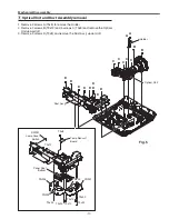
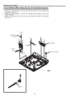
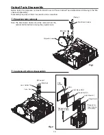
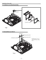
Filter Box and Terminal Cover removal
Mechanical Disassembly
Mechanical disassembly should be made following procedures in numerical
order.
Following steps show the basic procedures, therefore unnecessary step may
be ignored.
Caution:
The parts and screws should be placed exactly the same position as the origi-
nal otherwise it may cause loss of performance and product safety.
Screws Expression
(Type
Diameter x Length
) mm
T type
M Type
Fig.1
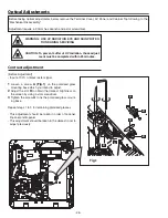
1. Slide the Filter Cover in the arrow direction and remove it.
. Pull out the Filter Box.
3. Remove screws A (T3x10) and then press and hold
hooks B on the Terminal Cover and pull it to remove.
Filter Cover
A
A
Filter Box
Terminal Cover
Note:
Do not disassemble the filter box to clean up or replace the parts inside of the filter
box. When replacing the filter, replace whole the filter box with new one to maintain the
projector's performance.
B
Bottom view
B
Содержание PRM-30A
Страница 57: ... 57 FA5550NG P F Control IC621 IC Block Diagrams L3E06200 D A S H LCD Driver IC501 IC531 IC561 ...
Страница 58: ... 58 IC Block Diagrams L3E07111 Digital Gamma and Driver IC401 LC87F2G08A PIC Micom IC9885 ...
Страница 59: ... 59 IC Block Diagrams MR4010 Power OSC IC631 NJW1156 Audio Selector IC5001 ...
Страница 65: ... 65 Parts Location Diagrams KJ8 30A00 LCD Panel Prism Assembly Relay lens Out assembly L01 S08 M07 L06 S09 ...
Страница 87: ...Key No Part No Description Key No Part No Description 87 Electrical Parts List KJ8 30A00 ...
Страница 88: ... KJ8YF Jun 2011 DC 50 Printed in Japan ...


