background image

7

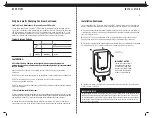
Installation Continued

7.

 Run your cables free from sharp objects and hold each of them in place with cable ties.

Coil excess cable, 

do not cut or shorten the length of the cables

 as there are in-line

fuses located 4 inches from the end of each positive (red) cable. These fuses are in place to
protect the charger and output cables in the event of a short or reverse polarity.

8.

 Connect the DC output cables as illustrated on page 8. Make sure the black wire is connected

as illustrated to the negative side of the battery and the red wires are connected to the positive
side of the battery.

9.

 Make sure all DC connections are tight and correct.

10.

 Locate the AC power cord in an open-air area of your boat at least 21 inches from the

charger, batteries and fuel fill lines.

11.

 Connect a heavy duty U.L. approved extension cord to the battery charger first. After

connecting the extension cord to the charger then proceed to plug the extension cord to
a nearby 120VAC GFCI protected (Ground Fault Circuit Interrupt) outlet. Always remove the
extension cord from the 120VAC outlet first when charging is completed, followed by
unplugging the charger.

You are now connected and charging your batteries. View the LED indicators. Assuming your
batteries are discharged you should observe both the blue "Power" LED and the red "Charging"
LED on, indicating charging mode is in process.

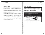
I N S TA L L AT I O N

8

When connecting each jacketed battery charger cable, make sure it is connected
to only 

one 12 VDC battery

 and observe the polarity and color of all connections:

Red Wire =  +  (Positive) Battery connection

Black Wire =  -  (Negative) Battery connection
The black wire can never be connected to a terminal with red wires. Only black.

Important: The pair of red and black wires in 1 cable jacket MUST GO TO THE SAME 12VDC battery.

Each charger cable

 must

be connected to 1 battery,
just as shown. Observe
black to (-) and red to (+).
Do this for each battery.

Top View of Battery

cable jacket

Group size 24

thru 31 only

red (+)

black (-)

+

_

Installation

When connecting to an engine start battery only connect the battery bank cable that is LABELED:
"FOR ENGINE BATTERY USE THIS BANK CABLE ONLY".

I N S TA L L AT I O N

ProMar1 Wiring Diagrams

IMPORTANT NOTICE

If only two batteries are used with a 3 bank charger, then connect the unused output 
cable to either one of the two batteries, as instructed in item 8 above

Always connect each charger output to a single 12V battery even if the batteries
are wired series for 24V or 24V with an engine battery.

Содержание 31405

Страница 1: ...oof Marine Battery Chargers ProSport Series Heavy Duty Recreational Grade Marine Battery Chargers ProTournament Series Professional Grade Tournament Grade Marine Battery Chargers ProIsoCharge Series Digitally Controlled Zero Loss Charging Isolators Digital Mobile Charge In Transit Chargers Battery Maintainers AC Plug Holders Battery Isolators Isolation Transformers Galvanic Isolators and Monitored...

Страница 2: ...our Batteries page 13 Maintenance page 14 Trouble Shooting page 15 Customer Service Warranty page 16 Selector Guide page 17 Accessories page 18 TA B L E O F C O N T E N T S Please save and read this manual carefully and fully understand the safety instructions before installing your new ProMariner On Board Marine Battery Charger ...

Страница 3: ...eneral Safety h Remove all personal metal items such as rings bracelets necklaces watches and jewelry when working near a battery A battery can produce a short circuit current high enough to weld a ring or any other metal causing serious burns Not intended to supply low voltage electrical systems other than in a marine application Do not use your marine battery charger to charge dry cell batteries...

Страница 4: ... buildup allowing your batteries to be fully charged and maintained until your next fishing trip General Overview The ProMar1 Battery Charger is a fully Automatic Electronic On board Marine Battery Charger The unit is prewired for easy installation and is 100 waterproof for fresh and salt water applications The ProMar1 charger incorporates a durable one piece plastic housing The unit offers fully ...

Страница 5: ... 5 volts finishing voltage that maintains each battery step down voltage regulation mode which is perfect for short or long storage periods and will never overcharge your batteries OV E RV I E W 6 Installation Continued vinyl or varnished areas Be sure to place the ProMar1 Battery Charger in an accessible area where all indicators are viewable Confirm all battery cables can reach each of the batte...

Страница 6: ...ger You are now connected and charging your batteries View the LED indicators Assuming your batteries are discharged you should observe both the blue Power LED and the red Charging LED on indicating charging mode is in process I N S TA L L AT I O N 8 When connecting each jacketed battery charger cable make sure it is connected to only one 12 VDC battery and observe the polarity and color of all co...

Страница 7: ...itive Battery connection Black Wire Negative Battery connection The black wire can never be connected to a terminal with red wires Only black Installation Output 2 AC power Output 1 ProMar1 5 3 5 5 ProMar1 Wiring Diagrams I N S TA L L AT I O N 9 red black _ When connecting each jacketed battery charger cable make sure it is connected to only one 12 VDC battery and observe the polarity and color of...

Страница 8: ...red black Cable 1 Bat 1 Bat 2 Bat 3 Cable 2 Cable 3 For Engine Battery use this Bank Cable Only _ _ I N S TA L L AT I O N ProMar1 Wiring Diagrams 11 Dual Output Charger for 2 12V Batteries Important Thepairofredandblackwiresin1cablejacketMUSTGOTOTHESAME12VDCbattery TopView ofBattery red black _ red black _ Bat 2 Bat 1 Cable 2 Cable 1 IndicatesJumperSeries Note IndicatesFuse Dedicated 24VDCTrolling...

Страница 9: ...nufacturer s recommendations for battery cell caps loosen caps if applicable 3 Connect a heavy duty U L approved extension cord to the ProMar1 charger first After connecting the extension cord to the charger then proceed to plug the extension cord to a nearby 120VAC GFCI protected Ground Fault Circuit Interrupt outlet 4 Observe the on board LED indicators for a solid blue and solid red LED Indicat...

Страница 10: ...all us at 1 800 824 0524 for technical support PROMAR1 LIMITED TWO YEAR FACTORY WARRANTY Each ProMite model is guaranteed against defects in material and workmanship to the original consumer in normal use for 2 years from the date of purchase Professional Mariner LLC will at it s discretion repair or replace free of charge any defects in material or workmanship The following conditions apply Warra...

Страница 11: ...odel 31408 12V 17 A C C E S S O R I E S Accessories Handheld DC System Tester 87710 n a n a n a Remote Battery Bank Status Monitor 51060 10 12 3 ProMariner AC Plug Holder white 51200 n a n a n a ProMariner AC Plug Holder black 51201 n a n a n a Universal AC Plug Holder black 51202 n a n a n a Universal AC Plug Holder white 51203 n a n a n a 15 Battery Bank Cable Extender 51070 15 n a n a 5 Battery...

Отзывы: