Fig 5
Firmly hold the spring cover (Y).
Pull out the cover and rotate until the pin
(Z) on the return spring plate engages
the next notch in the coil spring cover.
Turn the cover clockwise to decrease
tension and counter-clockwise to
increase tension.
Tighten knob (X).
7.6 Before Operation
Prepare oil gun with coolant or cutting
oil.
In order to keep the accurate precision,
the table must be free form dust and oil
deposites.
Check to see that the tools are correctly
set and the workpiece is set firmly.
Be sure the speed is not set to fast.
Be sure everthing is ready before use
7.7 After Operation
Turn off the electric switch.
Turn down the tools.
Clean the machine and coat it with
lubricant.
Cover the machine with cloth to keep
out the dust.
7.8 Adjustment of Head
To raise and lower the head, loosen the
two nuts (V, Fig 6) located on the right
side of the Z-slide.
Fig 6
Use the crank (Fig 7) to raise and lower
the head.
When the desired height is reached
tighten the 2 nuts to avoid vibration.
Fig 7
The head may be rotated 360º around
the column.
Loosen the 2 nuts (V, Fig 6).
Adjust the head, then well tighten the
nuts to avoid movement under
machining loads.
Fig 8
The head may be tilted left/right.
Loosen 3 nuts (U, Fig 8).
Tilt the head to the degrees you wish on
the scale, then well tighten the 3 nuts to
avoid vibration.
7.9 Preparing for Drilling.
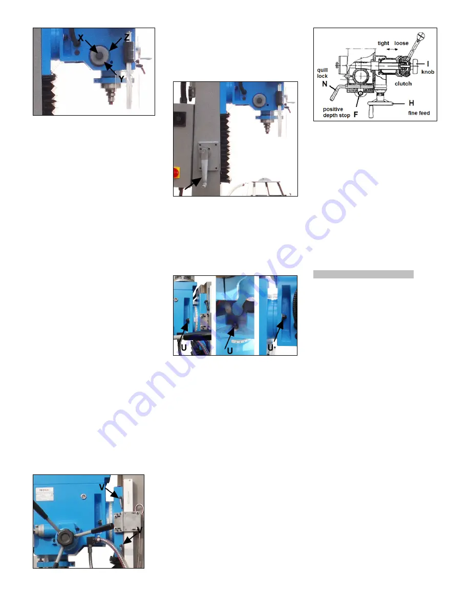
Loosen the quill lock (N, Fig 4, Fig 9).
Loosen the knob (I) to make loose the
taper clutch of worm gear, to disengage
the fine feed (H).
Set the positive depth stop (F) to the
desired drilling depth.
Fig 9
7.10 Preparing for Milling
Adjust the positive depth stop (F, Fig 9)
to highest point position.
Turn tight of the knob (I) to engage the
taper clutch, to engage the fine feed (H).
Turn the fine feed hand wheel (H) to
adjust the desired machining height.
Tighten the quill lock (N) to avoid
vibration.
8. Maintenance and inspection
General notes:
Maintenance, cleaning and repair
work may only be carried out after
the machine is protected against
accidental starting.
Push the emergency stop button and
disconnect from the power source!
Clean the machine regularly.
Defective safety devices must be
replaced immediately.
Repair and maintenance work on the
electrical system may only be carried
out by a qualified electrician.
8.1 Weekly Lubrication:
Weekly apply oil:
DIN 51502 CG ISO VG68
(e.g. BP Maccurat 68, Castrol Magna BD
68, Mobil Vectra 2)
- X-axis lead screw
Apply oil on entire length.
- Y-axis lead screw
Move the table forward and remove the
way cover for access.
Apply oil on entire length.
- Z-axis lead screw
Move the head up and remove the way
cover for access.
Apply oil on entire length.
Содержание JMDT-804516-DRO
Страница 9: ...JMDT 804516 DRO Headstock Assembly 1...
Страница 13: ...JMDT 804516 DRO BASE PARTS 2...


