background image

PIXIESPOT

12

Fig.6

Fig.7

3.5 CONNECTION OF THE DMX LINE

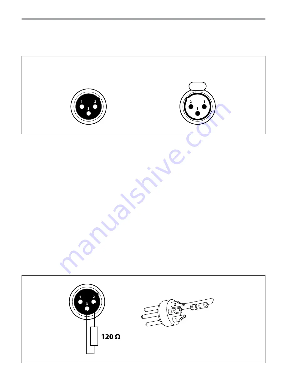
DMX connection employs standard XLR connectors. Use shielded pair-twisted cables with 120Ω imped-

ance and low capacity.

The following diagram shows the connection mode:

ATTENTION

The screened parts of the cable (sleeve) must never be connected to the system’s earth, as this would 

cause faulty fixture and controller operation.

Over long runs can be necessary to insert a DMX level matching amplifier. 

For those connections the use of balanced microphone cable is not recommended because it cannot 

transmit control DMX data reliably. 

•  Connect the controller DMX input to the DMX output of the first unit.

•  Connect the DMX output to the DMX input of the following unit. Connect again the output to the input 

of the following unit until all the units are connected in chain.

•  When the signal cable has to run longer distance is recommended to insert a DMX termination on the 

last unit.

3.6 CONSTRUCTION OF THE DMX TERMINATION

The termination avoids the risk of DMX 512 signals being reflected back along the cable when they reach-

es the end of the line: under certain conditions and with certain cable lengths, this could cause them to 

cancel the original signals.

The termination is prepared by soldering a 120Ω 1/4 W resistor between pins 2 and 3 of the 3-pin male XLR 

connector, as shown in figure.

DMX - OUTPUT

XLR socket

DMX - INPUT

XLR plug

Pin1 : GND - Shield

Pin2 : - Negative

Pin3 : + Positive

Example:

3 pin XLR connector

Содержание PIXIESPOT

Страница 1: ...USER MANUAL PIXIESPOT SPOT MOVING HEAD EN ...

Страница 2: ...y any means for any commercial use In order to improve the quality of products PROLIGHTS reserves the right to modify the characteristics stated in this instruction manual at any time and without prior notice All revisions and updates are available in the manuals section on site www prolightsamerica com ...

Страница 3: ...on of the DMX line 3 6 Construction of the DMX termination 3 7 DMX channels 3 8 DMX configuration 3 9 Autoshow 3 10 Focus adjustment 3 11 Motor settings 3 12 Fixture settings 3 13 Display settings 3 14 Fixture test 3 15 Reset functions 3 16 Fixture informations 4 Maintenance 4 1 Maintenance and cleaning the unit 4 2 Fuse replacement 4 3 Trouble shooting 2 2 4 4 6 7 8 8 9 12 13 13 14 17 17 17 17 18...

Страница 4: ...ed technical personnel Contact the nearest sales point for an inspection or contact the manufacturer directly If the unit is to be put out of operation definitively take it to a local recycling plant for a disposal which is not harmful to the environment Warnings and installation precautions If this device will be operated in any way different to the one described in this manual it may suffer dama...

Страница 5: ... optics Focus Motorised COLOR SYSTEM Color Mixing RGBW FC CTC Linear CTO correction 2700 6000K Color Wheel Virtual color wheel with presets DYNAMIC EFFECTS Rotating Gobos 7 Rotating gobos Open Interchangeable Gobo Size gobo Ø 16 9 mm img Ø 14 mm 2 mm Circular Prism 3 f with bi directional rotation Auto Mode Built in programs with execution speed adjustment Sound Mode Music activation through inter...

Страница 6: ...sumption at 230V 118 W Power Consumption at 120V 120 W Output at 230V 17 units on a single power line Output at 120V 9 units on a single power line PHYSICAL Signal Connection DMX 5p IN OUT Amphenol Power Connection IN OUT Neutrik Truecon IP 20 Cooling Forced air with low noise fan Suspension And Fixing Any position with quick lock omega brackets Dimensions WxHxD 253x352x192 mm Weight 7 kg Technica...

Страница 7: ...ction to a socket 100 240V 50 60Hz via the supplied mains cable 8 POWER OUT PowerCON OUT power output for connection of multiple units in series 9 MAIN FUSE HOLDER replace a burnt out fuse by one of the same type only 10 DMX IN 5 pole XLR 1 ground 2 DMX 3 DMX 4 N C 5 N C 11 DMXOUT 5 poleXLR 1 ground 2 DMX 3 DMX 4 N C 5 N C 1 3 OPERATING ELEMENTS AND CONNECTIONS Fig 2 View A View B spot 4 7 9 11 10...

Страница 8: ...the stop Always ensure that the unit is firmly fixed to avoid vibration and slipping while operating The mounting place must be of sufficient stability and be able to support a weight of 10 times of the unit s weight When carrying out any installa tion always comply scrupulously with all the regulations particularly regarding safety currently in force in the country in which the fixture s being us...

Страница 9: ...which can be switched on and off via light switch 3 2 BASIC The PIXIESPOT has a OLED display and 5 button used to access the control panel functions and manage them fig 4 Fig 4 Functions of the buttons and display icons UP DOWN LEFT RIGHT ENTER Increases the value displayed or passes to the previous item in a menu Decreases the value displayed or passes to the next item in the menu To enter in the...

Страница 10: ... Yes Tilt Inverse ð No Yes Motor Offset ð Pan Offset ð 000 255 Tilt Offset ð 000 255 Gobo Offset ð 000 255 Prism Offset ð 000 255 Focus Offset ð 000 255 4 System Setup Master Slave ð Master Slave Sound Sence ð 000 100 White Balance ð Red ð 125 255 Green ð 125 255 Blue ð 125 255 Dimmer Mode ð Off Dimmer 1 Dimmer 2 Dimmer 3 Fan Mode ð Auto Speed High Speed Factory Setting ð No Yes 5 Display Setup ð ...

Страница 11: ...e ð 000 255 Pan Tilt Speed ð 000 255 Dimmer ð 000 255 Shutter ð 000 255 Red ð 000 255 Green ð 000 255 Blue ð 000 255 White ð 000 255 Gobo ð 000 255 RGobo ð 000 255 Prism ð 000 255 RPrism ð 000 255 Focus ð 000 255 7 Reset Setup ð Auto reset Manual Reset ð Pan Reset ð No Yes Tilt Reset ð No Yes Gobo Reset ð No Yes Prism Reset ð No Yes Focus Reset ð No Yes ...

Страница 12: ...PIXIESPOT 10 8 Information ð FixtureTime ð 0 9999 SoftwareVersion ð DISP V 1 0 CTR XY V 1 0 CTR LED V 1 0 LEDTemperature ð 58 C ...

Страница 13: ...ess item Then press the button ENTER to confirm Press the buttons UP DOWN to select the desired value 001 512 Then press the button ENTER to con firm Press repeatedly the button LEFT to return the menu mode To able to operate the PIXIESPOT with a light controller adjust the DMX start address for the first a DMX channel If e g address 33 on the controller is provided for controlling the function of...

Страница 14: ...MX output of the first unit Connect the DMX output to the DMX input of the following unit Connect again the output to the input of the following unit until all the units are connected in chain When the signal cable has to run longer distance is recommended to insert a DMX termination on the last unit 3 6 CONSTRUCTION OF THE DMX TERMINATION The termination avoids the risk of DMX 512 signals being r...

Страница 15: ... 3 Seconds No function 000 199 200 209 210 255 7 7 7 RED 0 100 000 255 8 8 8 GREEN 0 100 000 255 9 9 9 BLUE 0 100 000 255 10 10 10 WHITE 0 100 000 255 11 11 COLOR No function Red Yellow Green Cyan Blue Magenta White Full Clockwise rotation Fast to Slow Stop Run Counterclockwise rotation Slow to Fast 000 007 008 022 023 037 038 052 053 067 068 082 083 097 098 112 113 127 128 189 190 193 194 255 11 ...

Страница 16: ... Slow to Fast 000 127 128 189 190 193 194 255 13 14 14 PRISM Prism Off Prism On Clockwise rotation Fast to Slow Stop Rotation Counterclockwise rotation Slow to Fast 000 010 011 127 128 189 190 193 194 255 14 15 15 STROBE Shutter Closed No Function Shutter open Strobe Effect Slow to Fast No function Shutter open Pulse effect in sequence No function Shutter open Random Strobe Effect Slow to Fast No ...

Страница 17: ... 4 Colours Fade 15 Colours Snap 15 Colours Fade Sound Control 000 010 011 070 071 130 131 190 191 250 251 255 20 AUTO PROGRAM SPEED Speed Slow to Fast SOUND SENSITIVITY Sound Sensitivity OFF Control the Sound Sensitivity 000 255 000 010 011 255 21 MOTOR SHOW No Function Motor Show 1 Motor Show 2 Motor Show 3 Motor Show 4 Motor Show 5 Motor Show 1 4 Motor Show 6 000 010 011 058 059 106 107 154 155 ...

Страница 18: ...er the menu mode Use the buttons UP DOWN to select the Show setup item Press the button ENTER Press the buttons UP DOWN to select the Focus adjust item Then press the button ENTER to confirm Press the buttons UP DOWN to select the desired values 000 255 Then press the button ENTER to save Press repeatedly the button LEFT to return the menu mode 3 11 MOTOR SETTINGS To change the unit parameters fol...

Страница 19: ...rticularly when set Off The increase in light intensity is linear Dimmer 1 Light intensity control is finger at low levels and coarse at high levels Dimmer 2 Light intensity control is finger at high levels and coarse at low levels Dimmer3 Light intensity control is finger at low levels and high levels and coarse at medium levels Fan Mode Fan speed Select the desired fan speed High Speed or Auto S...

Страница 20: ...hen press the button ENTER Press the buttons UP DOWN to select the item Autoreset Then press the button ENTER to confirm and to restart automatically Manual reset Press the button LEFT to enter the menu mode Press the buttons UP DOWN to select the item Reset Setup Then press the button ENTER Press the buttons UP DOWN to select the item Manualreset Then press the button ENTER to confirm Press the b...

Страница 21: ... frequency with which the following operations are to be carried out depends on various factors such as the amount of the effects and the quality of the working environ ment air humidity presence of dust salinity etc Use a soft cloth dampened with any detergent liquid for cleaning glass to remove the dirt from the reflectors from the lenses and filters It is recommended that the projector undergoe...

Страница 22: ... assembly Misaligned lens assembly Clean the fixture regularly Install lens assembly properly Fixture does not power up No power Loose or damaged power cord Faulty internal power supply Check for power on power outlet Check power cord Replace internal power supply Fixture does not respond to DMX Wrong DMX addressing Damaged DMX cables Bouncing signals Check control panel and unit addressing Check ...

Страница 23: ...Note ...

Страница 24: ......

Отзывы: