


13
Item
Exit
To do
Return Main Menu
Display setting
Display setting
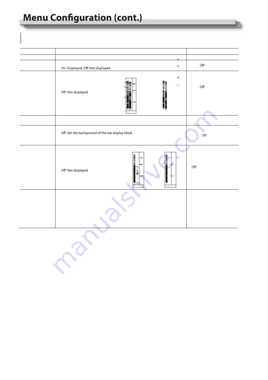
On: Displayed,
Setting value
Audio Setting
Setting for the audio meters and channel selection
On
、
On
、
Bar Frame*1
Bar Position
Bar Blending
Audio Alarm*2
Left Channel
Right Channel*3
Bar Position setting
Top Right
、
Bottom Left
、
Bottom Right
、
Top Left
Low
、
、
High
、
On
SDI
:
Channel 1
、
Channel 2
Bar Blending setting
Low: Set the background of the bar display gray
High: Set the background of the bar display transparent.
Display setting
On: Displayed,
Select the audio left and right
channels to output.
The current left channel
number displays green, and
the right channel number
displays red.
Audio Bar
-09
-20
-48
1 2
-04DB -06DB
Red
Yellow
Green
Bar Frame : On
1 2
Bar Frame : Off
-09
-20
-48
1 2
-04DB -06DB
Audio Alarm : On
Audio Alarm : Off
M
U
T
E
-09
-20
-48
1 2
-04DB -06DB
*1 When “Bar Frame” is set to “Off”, only the audio meter will be displayed;
When “Bar Frame” is set to “On”, frame and real-time audio value will be displayed.
*2 When “Audio Alarm” is set to “On”, if no embedded audio is detected, the audio bar will display “UNLOCKED”.
If the audio value is too low, the audio bar will display “MUTE”.
*3 Only under SDI signal, user can set the output channel as channel 1 or channel 2 according to requirements.
In audio bar, the left channel information will be in green, and the right channel information will be in red.
Содержание DT-N21H
Страница 22: ...22 MEMO ...