background image

TDR-26 

Operator’s Manual


33 


INTERMEDIATE BEARING 

– 8h / Daily (1 Location) 


Use  only  manual  pump-style  grease  guns  for  lubricating 
driveline  components.    Use  of  power  greasing  equipment  can 
induce  excessive  pressure  into  the  component,  compromising 
sealing  components  and  leading  to  premature  wear  and 
component failure. 

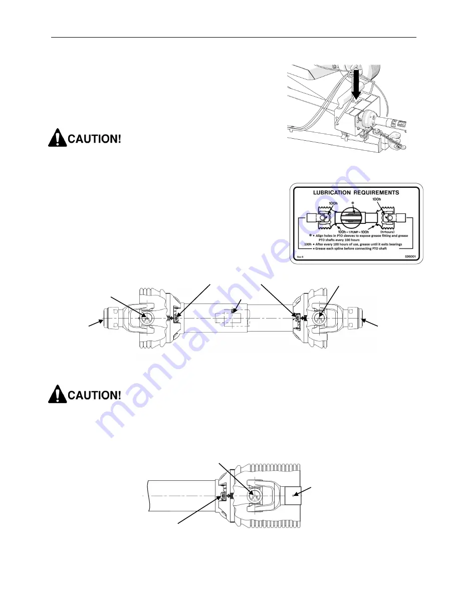
DRIVELINE GREASING 


Driveline  shafts  on  the  TDR-26  mower  feature  a  100  hour  grease 
interval.  The following decal located on the hose support shield as 
a reminder of the minimum requirement.  


INPUT & DECK SHAFTS 

– 100h / Monthly (7 / Shaft - 4 Shafts


Failure to properly lubricate the telescoping shaft sections will 
lead  to  binding  of  the  shaft  and  damage  to  the  mower  or 
tractor driveline. 

INTERMEDIATE SHAFT 

– 100h / Monthly (3 Locations) 


* Inner & outer guards must be rotated to align holes 

for accessing telescoping shaft grease fitting. 


TELESCOPING SHAFT*


GUARD BUSHINGS


CROSS & BEARINGS


CROSS & BEARINGS


SPLINE


SPLINE


CROSS & BEARINGS  

SLIP YOKE SPLINES  

GUARD BUSHINGS  

Содержание TDR-26

Страница 1: ...ist TDR 26 Rotary Finish Mowers Serial No 1826101 and up PROGRESSIVE TURF EQUIPMENT INC 137 WEST WILLIAM STREET SEAFORTH ONTARIO CANADA N0K 1WO TOLL FREE 800 668 8873 ISSUE DATE February 2019 P N 120593 www progressiveturfequip com ...

Страница 2: ......

Страница 3: ... DECALS 14 DECAL LOCATIONS 14 DECAL LISTING 15 ASSEMBLY INSTRUCTIONS 17 SET UP 17 MOWER DECKS 18 DECK PTO SHAFTS 19 INPUT SHAFT 20 TRANSPORT TIRES 20 BLADE INSTALLATION 20 MOWER SETUP FOR OPERATION 21 HITCH ADJUSTMENT 21 HITCHING THE MOWER TO THE TRACTOR 21 CONNECTING THE PTO DRIVELINE 22 CONNECTING THE HYDRAULICS 23 CONNECTING THE PULL ROPE 23 MOWER SAFETY LOCKS 23 CHECK PTO DRIVELINE DURING MANE...

Страница 4: ...or s Manual 2 V BELT DRIVE 35 FASTENER INSTALLATION TORQUE 36 BLADE SERVICING 37 SPINDLE SERVICE 40 HYDRAULICS 42 SUPPORTING MACHINE FOR SERVICE 42 TRANSPORT TIRES 43 LONG TERM STORAGE 43 TROUBLESHOOTING 44 NOTES 45 ...

Страница 5: ...e g PTO shafts etc refer to the respective documents included with the manual set for this machine The TDR 26 series are production turf grass finishing rotary mowers with a 22 foot cutting width and is designed to be pulled by a 65 75 PTO horsepower tractor High blade tip speed gives this versatile mower the ability to mow both slightly contoured and flat terrain that requires a high quality afte...

Страница 6: ..._______ _____________ Date purchased _____________ _____________ NOTE The last digit in each TDR 26 serial number is a letter This letter denotes the deck configuration of the mower Blank Painted Decks G Galvanized Decks REPLACEMENT PARTS INFORMATION Use only Genuine Original Equipment Manufacturers O E M replacement parts The use of will fit parts may reduce machine performance void machine warra...

Страница 7: ...authorized Modification or Misuse of a TDR 26 mower either past or intended it is the responsibility of that person to ensure that Progressive Turf Equipment Inc s Engineering Manager is notified of the occurrence promptly That person shall provide the facts of the occurrence location machine serial number name and contact information of the persons involved Send correspondence regarding Unauthori...

Страница 8: ...ow Blade Mounting Two bolts nuts per blade No internal threads Blade Speed 2914 rpm 18300 sfpm Rollers 6 6 Dia Heavy wall steel with replaceable shafts Roller Bearings Hex bore positive drive with triple lip seals Ductile Iron housing Ground Pressure 6 psi Power Transmission Input Shaft Cat 6 1 3 8 dia 6 Spline with auto locking collar Deck Drive Shafts Cat 3 1 3 8 dia 6 spline with quick connect ...

Страница 9: ...mined by standing at the rear of the equipment and facing the direction of forward travel PARKING JACK INPUT PTO SHAFT DRAW CLEVIS PULL ROPE DECK LIFT CYLINDERS DECK SAFETY LOCKS DECK ROLLER FRONT REAR EACH DECK DECK GEAR BOX TRANSPORT SAFETY CHAIN 4 WAY GEAR BOX HYDRAULIC CONNECTION DECK ADJUSTMENT WRENCH OPERATOR S MANUAL HOSE SUPPORT FRONT REAR ...

Страница 10: ...urer is used it is your responsibility to ensure that it is safe for you and others You should also ensure the machine will not be damaged or made unsafe by the operation maintenance or repair procedures you choose Modifications or adaptations to the machine are not allowed Various jurisdictions have specific requirements for work zone safety Know and adhere to your local requirements Treat the in...

Страница 11: ...nt that may be required Prolonged exposure to loud noise can cause hearing damage Never operate a mower while under the influence of drugs or alcohol These make reflexes slow and put you and others in grave danger Always make sure you have full concentration while mowing Adhere strictly to all regulations at the worksite pertaining to the operation of this equipment Always disengage power takeoff ...

Страница 12: ...nit and immediately check for the cause Excess vibration is generally an indication of a problem Replace bent or damaged parts do not attempt to straighten a bent blade Ensure that no bystanders are within 10 ft of mower when wing transport locks are released Keep all bystanders well away from the machine when it is operating Always maintain a safe operating distance from personnel other equipment...

Страница 13: ...ment bolts Check that all cotter pins are properly installed Keep equipment in good condition Keep mower free of grass leaves or other debris build up Never work on raised mower decks without safety locks in place Periodically check condition of safety devices guards and deflectors Replace only with manufacturer s recommended parts Inspect and replace damaged blades Use only original OEM parts Bla...

Страница 14: ...ill provide a weld metal strength equivalent to the parent material Move the machine to a clean safe area before welding grinding or using a cutting torch on it This type of work should only be done in a clean area and not in places that contain combustible liquids such as fuel tanks hydraulic pipes or similar Connect arc welder ground as close as possible to work area Work with extra care when we...

Страница 15: ...ng mower to tractor ensure hydraulic hoses have sufficient slack for negotiating turns and uneven terrain Immediately replace any hydraulic hose that shows signs of swelling wear leaks or damage so it does not burst Do not use your hand to check for hydraulic oil leaks Use a piece of cardboard instead Hydraulic fluid escaping under pressure can penetrate the skin causing serious injury If skin pen...

Страница 16: ... 8 13 CAUTION PTO ALIGNMENT 1 4 COMPANY NAME 1 14 WING DECK BELT LAYOUT 2 5 DANGER BLADE HAZARD 7 15 REAR DECK BELT LAYOUT 1 6 WARNING OEM PARTS 1 16 CE ROTATING DRIVELINE 5 7 CAUTION DISENGAGE PTO 1 17 DANGER ROTATING DRIVELINE 5 8 GREASING SCHEDULE 1 18 DANGER GUARD MISSING 5 9 PTO GREASING 1 19 WARNING BLADE HARDWARE 1 10 NOTICE HITCH SETUP 2 20 GREASE POINT 14 5 BOTH SIDES 11 12 5 1 2 10 6 9 8...

Страница 17: ...DECAL LISTING ITEM 1 ITEM 2 ITEM 3 209175 209171 209113 ITEM 4 ITEM 5 ITEM 6 521817 209173 209115 ITEM7 ITEM 8 ITEM9 521820 526003 526001 ITEM 11 209103 ITEM 10 ITEM 12 ITEM 13 521784 209179 209189 PROGRESSIVE TDR 26 ROLLER MOWER ...

Страница 18: ...TDR 26 Operator s Manual 16 ITEM 14A ITEM 14B ITEM 15 530085 530087 527383 ITEM 16 ITEM 17 ITEM 18 210238 210239 210237 ITEM 19 GREASE POINT DECAL 209196 521014 ...

Страница 19: ...re shipped stacked on steel legs deck rollers side channels are shipped on separate pallets All other components are packaged with the main frame The machine parts list can be used as a graphical reference for assembly Approximately 1 1 2 hours domestic or 3 1 2 hours overseas are required to complete the mower to field ready condition Assembly will be easier if components are aligned and loosely ...

Страница 20: ...etain the painted 1 1 4 pins shipped in the deck swivel bushings 4 Connect the mower to a hydraulic supply Retract the hydraulic cylinders and release the deck locks Never retract the wing cylinders into the lift and turn position when the decks are not attached to the wings You will damage the wing and lock components the force the cylinders supply is too great without the counterweight of the de...

Страница 21: ...orientation shown with yokes installed flat NOTE Some guards have been removed in illustration for better clarity Ensure all guards are reinstalled before operating mower Failure to install deck PTO shafts with proper phasing can lead to failure of PTO shaft yoke s and or the gear box when decks are raised into transport position All PTO shafts feature non rotating guards that require proper tethe...

Страница 22: ...red spacer ring is in place between the input shaft yoke and hanger bearing race 5 Reinstall UNF retaining bolt in input shaft yoke torque to 85 ft lb 6 Reinstall input shaft shield per input shaft service instructions 7 Fasten input shaft guard retaining chain to mower main frame with sufficient slack as to not bind or pull during turns TRANSPORT TIRES 1 Check air pressure in the tires and adjust...

Страница 23: ... the PTO shaft to the top of the drawbar 3 The main frame of the mower should be level when hitched to the tractor 4 The draw clevis can be mounted in 2 positions flip over for adjustability 5 Using the supplied spacers adjust the height of the hanger bearing mount so that the input PTO shaft is in line with the tractor PTO HITCHING THE MOWER TO THE TRACTOR Crushing Hazard between tractor and mowe...

Страница 24: ... against the end of the tractor PTO shaft rotate either the tractor PTO or input driveline by hand until the shaft slides on slightly 5 Slide the yoke fully onto the tractor s PTO the locking collar should automatically engage when the yoke is properly engaged with the tractor PTO 6 Attempt to move the shaft forward and backwards to ensure that it is securely locked in place 7 Attach the PTO cover...

Страница 25: ...G THE PULL ROPE The TDR 26 mower is equipped with a nylon pull rope that is connected to the wing deck release mechanism used for locking the mower decks into transport position Connect it to the tractor in a position that is easily accessible to the operator and will release easily if the mower should ever become disconnected from the tractor MOWER SAFETY LOCKS Safety locks are provided for each ...

Страница 26: ...extend or collapse the PTO shaft The operator should avoid making sharp turns on uneven terrain If the PTO over extends it will come apart and can cause injury to the operator or damage to the mower or tractor If the input PTO shaft collapses fully it will force the shaft back against the hanger bearing This will cause damage and premature failure of the bearing CHECK TIRE CONTACT DURING TURNS The...

Страница 27: ...rom rear of tractor and hook on hose support rod 8 Disconnect hydraulic couplers from tractor stow in supplied locations in the sides of the hose support 9 Disconnect the transport safety chain from the tractor 10 Disconnect input shaft guard chain from tractor Slide the mower input shaft locking collar backwards opening the locking mechanism Locking collar should remain in an open position 11 Rem...

Страница 28: ...properly secured and will not become entangled in PTO shaft 10 Ensure deck lock system is functioning properly Page 26 DECK LOCK SYSTEM The deck lock system on the TDR 26 mower is a multi function system controlled by the pull rope Deck lock plates are activated by the pull rope and engage with the mower wings rear lift arm in different positions to provide a variety of functions As with any mecha...

Страница 29: ...position is present on the wings only the rear deck will be raised to transport position for washing Ensure the lock pin is in the position shown when using this function Never stand beneath the mower decks when placed in the wash down position PRO LIFT N TURNTM See Page 29 If it is not desired to use the Pro Lift N TurnTM system it is possible to disable it by inserting the lock pin in the positi...

Страница 30: ... for the decks to settle against the locks during storage or transport It may be necessary to raise the decks in order to disengage the locks ADJUSTING THE CUTTING HEIGHT Each of the three independent mower decks has its own cutting height adjustment Cutting height is set via an easy to use jack screw system on each corner of the deck A combination 1 wrench 15 16 socket tool is proved with the mac...

Страница 31: ... suitable ground speed gear to maintain proper cutting OPERATING ON HILLY TERRAIN When operating on hilly terrain proceed with caution and drive carefully If the tractor has four wheel drive make sure it is engaged On two wheel drive tractors equipped with a differential lock apply while driving straight on the hill disengage to allow for normal turning Use care while turning on hillsides in wet c...

Страница 32: ...transporting the TDR 26 from site to site ensure the wings are in the raised position and deck safety locks are engaged Page 26 Ensure the transport safety chain is properly fastened to the tractor Page 21 Ensure SMV placard is clean and all loose debris has been removed from the mower before transporting Observe the maximum allowable transport speed dependent on towing vehicle weight Towing Vehic...

Страница 33: ...ooth running machine for many years Some pivot locations have grease fittings The following information shows and describes where lubrication points are located and what types of lubricant are required Lubrication Intervals Service Initial Run 50h Daily As Req d 100h Monthly 600h Yearly Grease Intermediate Hanger Bearing X Deck Pivots X Transport Wheels X Wing Pivots X Wing PTO Shaft 7 locn s each...

Страница 34: ...nated and the lubrication properties may be lost leading to component damage 2 Molybdenum Disulfide Moly is an additive used in slow moving extreme load applications The particles in the Moly will actually increase bearing wear in a high speed mower application Generally speaking Moly based greases will be grey in colour 3 If synthetic base oil is used rather than mineral base oil the grease will ...

Страница 35: ...a 100 hour grease interval The following decal located on the hose support shield as a reminder of the minimum requirement INPUT DECK SHAFTS 100h Monthly 7 Shaft 4 Shafts Failure to properly lubricate the telescoping shaft sections will lead to binding of the shaft and damage to the mower or tractor driveline INTERMEDIATE SHAFT 100h Monthly 3 Locations Inner outer guards must be rotated to align h...

Страница 36: ...l is taken without threading dipstick into gearbox If the level is low add oil through dipstick port until correct level is attained Replace and tighten dipstick Changing Oil 600h Yearly The gearbox oil should be changed after the first 50 hours of operation and every 600 hours or yearly afterwards Oil change quantity 1 37 Qt 1 3 Litres 4 WAY GEAR BOX Checking Level 100h Monthly A screw in dipstic...

Страница 37: ... hours of operation is the belt run in period To ensure satisfactory belt performance belt tension should be checked during this time period V BELT ADJUSTMENT Each mower deck has 2 belts to transmit power from the gear box to the blade spindles Each drive belt utilizes an adjustable sliding tensioner idler to set belt tension In the event that belt adjustment must be made follow these steps for ea...

Страница 38: ...e 5 fasteners are to be used in the assembly of this machine unless otherwise specified in this manual Bolt Grade Identification SAE Grade 2 SAE Grade 5 SAE Grade 8 No Dashes 3 Dashes 6 Dashes Bolt Diameter Recommended Torque in Foot Pounds Newton Meters 5 16 UNC 21 28 3 8 UNC 38 52 7 16 UNC 55 75 1 2 UNC 85 115 9 16 UNC 125 170 5 8 UNC 175 240 3 4 UNC 300 410 7 8 UNC 450 610 1 UNC 680 925 1 14 LH...

Страница 39: ...BE DANGEROUS BLADE SELECTION We offer four blade styles for use with this mower Fixed high lift Combined with Progressive s high tip speed the fixed High Lift blade stands grass blades up for a clean cut even in damp conditions or at high mowing speeds Fixed low lift Developing less lift than the High Lift blade Progressive s Low Lift fixed blade is ideal for both new growth or sandy soils where a...

Страница 40: ...during sharpening Always balance blades before use In abrasive soil conditions monitor condition of the blade wing If erosion of the steel is evident at the base of the wing replace blade Pro EZ CHANGE BLADE REMOVAL AND INSTALLATION Blade Bar A 1 diameter pilot centers the blade bar on the spindle with two 1 2 grade 5 fasteners When changing blades be sure that pilot is properly seated in the blad...

Страница 41: ...ade bar may prevent the tip from pivoting properly at start up or during mowing Ensure all tips are free to rotate prior to operation BLADE SHARPENING Use gloves when handling mower blades Blades can be very sharp When sharpening blades be sure material removed is equal on both sides of the blade Unbalanced blades will cause excessive vibration leading to cracks in machine components Clean all mat...

Страница 42: ...ion 2 Relieve belt tension and remove belt from the spindle pulley 3 Place a piece of cardboard or other soft material on the ground beneath the spindle to be removed 4 From above the deck loosen remove the four nuts that hold the spindle assembly to the deck The spindle assembly will drop on to the ground 5 Remove the complete spindle assembly from beneath the deck SPINDLE ASSEMBLY INSTALLATION R...

Страница 43: ... bearings from spindle housing causes permanent damage to the bearings New bearing must be used in re assembling the spindle 21 Inspect bearing 8 spacer for wear If any wear is present replace spacer with new IMPORTANT Failure to replace a worn or damaged spacer will lead to premature top bearing wear 22 Place housing 7 in press upside down Pressing on outer race install bottom bearing 9 into hous...

Страница 44: ...r ends are clean Dirt in the hydraulic system can block the orifice in the line throttle valve or cause premature wear failure of hydraulic components on the mower or tractor SUPPORTING MACHINE FOR SERVICE 2 Points are available to lift the mower off of the ground for servicing the transport tires wheels bearings at the main frame rail just in front of the transport tires as shown in the accompany...

Страница 45: ...ng maintenance steps are followed 1 Thoroughly wash mower removing all grass clipping residue from deck undersides mower framework Ensure deck drain holes are free from debris 2 Add grease to all grease points 3 Check gearbox oil for proper level 4 Relieve tension on all V belts 5 Inspect all drive belts pulleys 6 Inspect all blade spindle bearings for excessive play and smooth operation 7 Inspect...

Страница 46: ...aring failure Over heating See Above Improper rebuild procedure See specific instructions in manual Page 40 Improper bearings Use only OEM bearings Water Ingress Avoid direct spray on bearing during washing Ensure drain holes on decks are not clogged Deck safety locks will not engage Wing not raising fully to release lock Decrease center distance retracted length of cylinder with adjustable clevis...

Страница 47: ...__ ___________________________________________________ ___________________________________________________ ___________________________________________________ ___________________________________________________ ___________________________________________________ ___________________________________________________ ___________________________________________________ _________________________________...

Страница 48: ...TDR 26 Operator s Manual 46 ...

Страница 49: ...Parts List TDR 26 Effective serial number 1826101 and up P N 120593 Issue Date February 2019 Si No Lee Ingles Pida Ayuda a Alguien Que Se Lo Lea Para Que le Traduzca Las Medidas de Seguridad ...

Страница 50: ......

Страница 51: ... 1 7 WING DECK DRIVE 7 1 8 REAR DECK ASSEMBLY 8 1 9 REAR DECK SHIELDS 9 1 10 REAR DECK DRIVE 10 2 FRAME ASSEMBLY 11 2 1 FRAME ASSEMBLY 11 2 2 WING LOCKS 12 2 3 WING ASSEMBLY 13 2 4 REAR LIFT ASSEMBLY 14 2 5 WHEEL ASSEMBLIES 15 3 HYDRAULICS 16 3 1 HYDRAULICS 16 4 DRIVELINE 17 4 1 DRIVELINE 17 4 2 DECK PTO SHAFT 18 4 3 INTERMEDIATE PTO SHAFT 19 4 4 INPUT PTO SHAFT 20 4 5 DECK GEARBOX 21 4 6 4 WAY GE...

Страница 52: ...TDR 26 Parts List ...

Страница 53: ...ed ______________ Always state this information when contacting your selling dealer and when ordering spare parts Parts Information Use only Genuine Original Equipment Manufacturers O E M replacement parts The use of will fit parts may reduce machine performance void machine warranties and present a safety hazard Use Genuine OEM parts Progressive Turf Equipment Inc 137 West William Street Seaforth...

Страница 54: ...ks before performing maintenance Block and or support machine using equipment designed for the task When maintaining blades or spindles always ensure locks are seated correctly in place When performing hydraulic maintenance ensure that pressure has been released It is imperative that the operator or qualified service technician reads and understands all the safety information in the Operator s Man...

Страница 55: ...e Name and Address of the person or organization ordering the parts who should be charged and if possible the serial number of the machine for which the parts are being ordered 3 The purchase order must clearly list the quantity of each part the complete and correct part number and the basic name of the part 4 The manufacturer reserves the right to substitute parts where applicable 5 Some parts ma...

Страница 56: ...TDR 26 Parts List iv ...

Страница 57: ...TDR 26 Parts List 1 1 DECK ASSEMBLY 1 1 Blade Spindle Assembly ...

Страница 58: ...TDR 26 Parts List 2 1 2 Blade Options ...

Страница 59: ...TDR 26 Parts List 3 1 3 Wing Deck Gear Box Mount ...

Страница 60: ...TDR 26 Parts List 4 1 4 Rear Deck Gear Box Mount Assembly ...

Страница 61: ...TDR 26 Parts List 5 1 5 Wing Deck Assembly ...

Страница 62: ...TDR 26 Parts List 6 1 6 Wing Deck Shields ...

Страница 63: ...TDR 26 Parts List 7 1 7 Wing Deck Drive ...

Страница 64: ...TDR 26 Parts List 8 1 8 Rear Deck Assembly ...

Страница 65: ...TDR 26 Parts List 9 1 9 Rear Deck Shields ...

Страница 66: ...TDR 26 Parts List 10 1 10 Rear Deck Drive ...

Страница 67: ...TDR 26 Parts List 11 2 Frame Assembly 2 1 Frame Assembly ...

Страница 68: ...TDR 26 Parts List 12 2 2 Wing Locks 2 2019 ...

Страница 69: ...TDR 26 Parts List 13 2 3 Wing Assembly ...

Страница 70: ...TDR 26 Parts List 14 2 4 Rear Lift Assembly ...

Страница 71: ...TDR 26 Parts List 15 2 5 Wheel Assemblies 10 2018 ...

Страница 72: ...TDR 26 Parts List 16 3 HYDRAULICS 3 1 Hydraulics ...

Страница 73: ...TDR 26 Parts List 17 4 DRIVELINE 4 1 Driveline ...

Страница 74: ...TDR 26 Parts List 18 4 2 Deck PTO Shaft ...

Страница 75: ...TDR 26 Parts List 19 4 3 Intermediate PTO Shaft ...

Страница 76: ...TDR 26 Parts List 20 4 4 Input PTO Shaft ...

Страница 77: ...TDR 26 Parts List 21 4 5 Deck Gearbox ...

Страница 78: ...TDR 26 Parts List 22 4 6 4 Way Gear Box ...

Страница 79: ...ng Part below Complete decal kits are also available TDR 26 DECAL KIT 530040 1 209175 DECAL GENERAL SAFETY 521819 DECAL CAUTION 209113 DECAL REPLACE SHIELDS 209173 DECAL ROTATING BLADE DANGER 521817 DECAL PROGRESSIVE TURF 209115 DECAL OEM PARTS 521820 DECAL CAUTION 521784 DECAL NOTICE 209103 DECAL PROGRESSIVE 209196 DECAL BLADE HARDWARE ...

Страница 80: ...ASE 526003 DECAL GREASING SCHEDULE 209197 DECAL TDR 26 ROLLER MOWER 521014 DECAL GREASE GUN 521455 DECAL OUTER SHIELD 210239 DECAL INNER GUARD 210238 DECAL CE WARNING 530085 RH WING DECK BELT LAYOUT 527521 REAR DECK BELT LAYOUT 530087 LH WING DECK BELT LAYOUT 2 2019 ...

Страница 81: ...________________________ ___________________________________________________________________________________________ ___________________________________________________________________________________________ ___________________________________________________________________________________________ ___________________________________________________________________________________________ _______...

Отзывы: