


ProgressiveIndustries.net | 800.307.6702
8
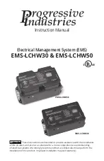
INSTRUCTION MANUAL:
ELECTRICAL MANAGEMENT SYSTEM (EMS)
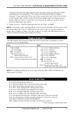
Note: If the EMS cuts the power to the RV it will show a PE code following the E code.
This denotes the previous error or why the EMS shut down. Example: The EMS cuts
power for low voltage on Line 1, and then the power is restored. The Error Code reads
E 0
, but the PE code reads PE 4 which tells the user low voltage was the reason for
the EMS previously cutting power. This PE error code will be deleted when power is
disconnected from the EMS.
Accidental 240 volt Protection: Should this condition occur, the display will read 240
volts instead of displaying the voltage and the error code message will read
E 3
. AC
power will shut down instantly.
DO NOT UNDER ANY CIRCUMSTANCES BYPASS THE
EMS; OTHERWISE, THIS WILL RESULT IN SEVERE DAMAGE TO THE RV.
Troubleshooting Guide
Common installation mistakes:
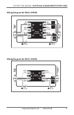
1) Check connections. Input is the plug side of the RV and black should be attached
to L1, white to L2. Output (going to the RV) should match up. T1 is black, T2 white.
The green ground get attached to the input and output on the side of the box.
2) Make sure the input wires are, in fact, the input wires. Connecting the output
to the input of the EMS will cause the device to malfunction.
3) If the EMS is still not functioning at this point, follow instructions below prior
to calling Progressive Industries Technical Support.
In order for the on-call Technician to help troubleshoot the problem(s) you are
experiencing and render the best possible solution, it is necessary you be at your
RV when you place your call.
1) If the display is illuminated and scrolling information, note the Error Code. If
there is an Error code of 1-9, the device will interrupt the power. See Error Chart
for definition of AC power problem. The device being off when an Error Code is
present indicates the product is working properly and protecting your coach.
2) If the display is illuminated and reading Error code
E 0
, and yet no power is
present in the coach, please contact Technical Support. You must wait for the
time delay light to stop flashing.
3) If the display is not illuminated and power is in the coach there is a connection
issue between the display and the main control box. Contact Technical Support.
Technical Support can only help if the above information is provided; therefore,
please do not call until this information is obtained. Again, it is necessary for your
to be at the RV when you place your call. To recap...
1) Are the connections correct?
2) What is the Error Code message being displayed?
3)
Is the delay indicator flashing?


