Progressive Industries EMS-LCHW30 Скачать руководство пользователя страница 7

ProgressiveIndustries.net    |    800.307.6702

7

INSTRUCTION  MANUAL:  

ELECTRICAL MANAGEMENT SYSTEM (EMS)

number indicates how many amps the RV is drawing. Next, you will notice “60H”, 

indicating your line frequency. This number should remain fairly consistent; 

however, it may read plus/minus one or two. Lastly, note the E code. 

E 0

 is normal 

and only when 

E 0

 or 

E 10

 is present will the delay light flash and allow power to 

the RV. Refer to the Error code chart card that was provided or see Error Code 

Chart for additional information.

5)  Verify the error code 

E 0

 is displayed and set up is now complete.

NOTE: 

If the wiring reads anything different than correct, the EMS will not turn on and 

we recommend you move to a different source of AC power or use your generator 

power. Also, if power is below 104 volts or above 132 volts, the EMS will not turn on, 

and we recommend using your generator power.
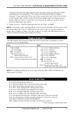
Display Code Chart 

The EMS display will indicate multiple electrical characteristics. Examples of these 

characteristics are listed below:

30A

50A

120 -

 Voltage


7A -

 Amperage


60H -

 Frequency


E0 -

  Error Code = 0  

(Normal operation)


PE3 -

  Previous Error Code = E3  

(This error has been corrected)

L1 -

 Line 1 Characteristics


120 -

 Line 1 Voltage


7A -

 Line 1 Amperage


L2 -

 Line 2 Characteristics


118 -

 Line 2 Voltage


5A -

 Line 2 Amperage


60H -

 Frequency


E0 -

  Error Code = 0  

(Normal operation)

  PE X -

  Previous Error Code = E3  

(This error has been corrected)

NOTE: If the display indicates an error code other than 

E0

 or 

E10

, the EMS will not 

allow power to the RV.

Error Code Chart

E 0 - 

Normal Operating Condition

E 1 - 

Reverse Polarity (hot and neutral wires reversed)

E 2 - 

Open Ground (no ground wire connection)

E 3 - 

Line 1 High Voltage (line voltage above 132V)

E 4 - 

Line 1 Low Voltage (line voltage below 104V)

E 5*- 

Line 2 Voltage High (line voltage above 132)

E 6*-

 Line 2 Voltage Low (line voltage below 104 volts)

E 7 - 

Line Frequency High (line frequency above 69 cycles per second)

E 8 - 

Line Frequency Low (line frequency below 51 cycles per second)

E 9 - 

Data Link Down (call technical support)

E10 -  

Replace Surge Protector Module (call technical support) 

* Codes only apply to EMS-LCHW50 models

Содержание EMS-LCHW30

Страница 1: ...ese instructions are intended to provide assistance with the installation of this product and are not a substitute for a more comprehensive understanding of electrical systems We strongly recommend that a certified electrician perform the installation of this product Improper installation may void warranty ...

Страница 2: ...the EMS needs to be serviced Reverse Polarity Protection If AC power has a reverse polarity condition the EMS will not allow power to the RV and the error code will read E 1 Open Neutral Protection If AC power has an open neutral the display will not light and the EMS will not allow power to the RV Open Ground Protection If AC power has an open ground condition the EMS will read an error code of E...

Страница 3: ...ction Do not modify the EMS in any way as this will void the warranty compromise protection and could result in possible shock and or a fire hazard It is important to always check the pedestal power outlet for charring this condition means the AC receptacle is providing a weak connection Should this condition exists DO NOT USE as it could result in possible melting of the RV power plug Progressive...

Страница 4: ...ng from the junction box by sliding it through the wire restraint output side of the EMS control box Next slide the black wire through the current sensor containing the green mark and connect to T1 then connect the white wire to T2 Next slide the red wire through the other sensor and attach to T3 The current sensor s can be oriented in either direction Attach the green ground wire to the ground sc...

Страница 5: ...0 wire for LCHW30 models and 6 wire for LCHW50 models Surge Electrical Protection units are for Recreational Vehicles RV only 1 Unplug RV from the AC power and be sure generator is off 2 Locate transfer switch box determine where the EMS control box will be mounted 3 Measure the distance between the transfer switch and the control box and add one 1 foot This is the length of cable that will be req...

Страница 6: ...ctory setting is for 15 seconds Remove jumper to change setting to 136 seconds 02 16 See Features Section on time delay to determine which to use See visual references on page 9 14 Plug in digital remote and data cable this cable is not a phone cable but rather a data cable NEVER PLUG IN THE DISPLAY WHILE RV POWER IS ON 15 Attach lid with the six black machine screws provided and attach transfer s...

Страница 7: ...characteristics Examples of these characteristics are listed below 30A 50A 120 Voltage 7A Amperage 60H Frequency E0 Error Code 0 Normal operation PE3 Previous Error Code E3 This error has been corrected L1 Line 1 Characteristics 120 Line 1 Voltage 7A Line 1 Amperage L2 Line 2 Characteristics 118 Line 2 Voltage 5A Line 2 Amperage 60H Frequency E0 Error Code 0 Normal operation PE X Previous Error Co...

Страница 8: ...he output to the input of the EMS will cause the device to malfunction 3 If the EMS is still not functioning at this point follow instructions below prior to calling Progressive Industries Technical Support In order for the on call Technician to help troubleshoot the problem s you are experiencing and render the best possible solution it is necessary you be at your RV when you place your call 1 If...

Страница 9: ...ProgressiveIndustries net 800 307 6702 9 INSTRUCTION MANUAL ELECTRICAL MANAGEMENT SYSTEM EMS Visual References Photo Library for the EMS LCHW50 ...

Страница 10: ...ProgressiveIndustries net 800 307 6702 10 INSTRUCTION MANUAL ELECTRICAL MANAGEMENT SYSTEM EMS Photo Library for the EMS LCHW30 ...

Страница 11: ... EMS LCHW30 Power Input Coach Load Output Black Output White Output Black Input Input Ground White Input Red Input Red Output L2 T2 L3 T3 L1 T1 Relay Contactors Output Ground Sensor w green mark Sensor Black Output White Output Black Input Input Ground White Input L2 T2 L1 T1 Relay Contactors Output Ground Sensor Power Input Coach Load Output ...

Страница 12: ...tries net 800 307 6702 ZX481 PRI 6007 1221 Progressive Industries Inc For more information regarding the Limited Lifetime Warranty Troubleshooting and the Warranty Claim Form visit www progressiveindustries net Technical Support 800 307 6702 tech progressive oneasg com ...

Отзывы: