REHATEAM s.r.l.—vicolo Negrelli 5—31040 Castagnole di Paese TV
-
www.rehateamprogeo.com
Service Manual JOKER 20
SERVICE MANUAL
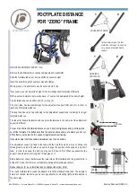
FOOTPLATE DISTANCE WITH 7° FRAME
G
TUB
E
TU
BE
20 mm
fixing
A
fixing
C
X1
X2
X3
DP
3 2 1
7°
7°
90°
A
C
B
D
F
C
A
20 mm
The particular characteristic of this MODEL is the 7° front frame taper.
As it is visible from the picture, the longer the footplate distance
DP
, the
narrower the room
X
between the two frames at footplate’s level.
According to that, when adjusting the footplate distance, it is necessary to
keep the 7° taper and increase or decrease the room
X
.
After adjustment, the forks have to be perpendicular to the ground. That will
tell you keep the 7° frame taper.
All footplates available for this model allows for such adjustment.
HEIGHT ADJUSTMENT EVERY 1.5cm
Remove the bolts
A
and their corresponding nuts and washers
B
.
Slide the footplate tube up or down until the necessary height.
Insert the bolts through the nearest holes and tighten.
Where present, it is possible to use the second hole
C
, too.
To reach short footplate distances, one can, both at original assembly or
afterwards, cut off the frame just below the fork support (regardless its posi-
tioning).
It should be clear that the possible adjustment may then be limited.
After adjustment, check that between the lower side of the footplate and the
ground there is at least 2 cm and that there is no interference between foot-
plate and casters.
Rubber adaptor for round footplate tube on elliptical tube (from 2019).
The round footplate tube needs the adaptor
F
to fit the elliptical frame tube.
The adaptor’s hole is not centred, therefore, you have to pay attention to
mounting right and let adaptors in the same way.
•
If the centre of the fixing hole
A
is at 20 mm from the lower extremity of
the frame tube, the adaptor
F
is usually mounted with its narrower side
facing frontward. In order to avoid squeezing the adaptor too much, do not
tighten the bolt very hard.
•
If the centre of the fixing hole
A
is further than 20 mm, thus even the hole
C
, the adaptor
F
is glued to the frame and assembled with its narrower
side backward. This is due to the fact that when you tighten the bolt, the
tube will lean against the inner side (which is very close) of the frame tube
and that guarantees the stability of the system. The bolt for this fixing in-
cludes a spacer
G
under the bolt’s head. This way, the bolt will run in be-
yond the frame tube wall; if so, it would impede the correct fixing of the
footplate tube. (This fixing is of course also possible if the point
A
is at 20
mm).
•
To turn the adaptor, (if it is not glued), remove the footplate tube, slide the
adaptor off and mount it reversed.
With elliptical footplate tubes, the adaptor is not present.


