progeo JOKER R2 Скачать руководство пользователя страница 7

REHATEAM s.r.l.—vicolo Negrelli 

5

31040 

Castagnole di Paese TV  

-

 www.rehateamprogeo.com


Service Manual JOKER R2    7


SERVICE MANUAL 

DIRECTIONALITY


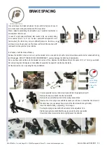
ADJUSTING THE DIRECTIONALITY 

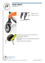
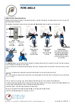
Check that the two forks are perpendicular to the ground. If they are not, 
proceed with the adjustment of the fork angle following the instructions 
on the sheet FORK ANGLE ADJUSTMENT. 

If both forks axis are correct but the wheelchair still turns right or left, it 
means that the latitudinal angle is not perfect. 

This may be due to hit, to improper pressure exercised on the fork or its 
support, or to a tiny imperfection among all parts fixed together due to 
their manufacturing tolerances. 

You can fix the fork axle 

in three different angles to correct the direc-

tionality.  

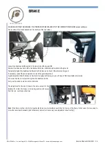
Loosen all four grab screws 

G

, remove the bolt 

F

 and slide off the fork 

complete with the axle 

P

The axle has two side hollows 

B

 where you have to cast the flat inserts 

C0 

or the 1° titled inserts 

C1 

that are recognizable thanks to two dots. 

With the flat inserts 

C0

, the axle keep its original inclination. 

With  the  tilted  inserts 

C1

,  the  axle  tilts  by  1°  right  or  left  according  to 

how to cast them in the hollows

see images.  

Note: you can cast the inserts only as indicated in these images.  

Once  you  have  casted  the  inserts 

C0

  or 

C2

,  it  is  advisable  to  try  to 

screw the bolt 

F

 to check there is no difficulty. Sometimes, in fact, the 

holes of the inserts may have working burr that make the bolt hard to go 
through.  

To mount the fork unit. Insert the axle 

P

 in the fork support paying atten-

tion to the orientation of the same axle. In fact, the axle is not straight, 
but it shows a bend. Such bend must be facing to the rear of the wheel-
chair.  

Insert and screw the bolt 

F

 without tightening it much (it is enough to screw it up to stop). 

Adjust the fork angle 


see sheet “fork angle”.  


Note. This type of adjustment can take place even at original assembly, therefore, you may find the in-
serts 

C0

 on one axle and 

C1

 on the other, for instance.  

The wheelchair is not supplied with supplementary inserts, therefore, it will be necessary to order them 
when needed. 


Axles without inserts 

Until 2019 the axles had no inserts 

C0

 or 

C1. 

There were 0°, 1°rh and 1°lh axles. 

To adjust the directionality, it is necessary to change the axle. 


B


P


0° 

X


Y

         1° 

Y               X                X               Y


X               Y                Y               X


          0°                                 1°                                    1° 

P                    P                     P


C0


C1


F


G3


F


G1 
G2


SIDE VIEW 


FRONT             REAR 

C0 

o

 C1  

P  

C0 

or


C1  

C0 

or


C1  

Содержание JOKER R2

Страница 1: ...REHATEAM s r l vicolo Negrelli 5 31040 Castagnole di Paese TV www rehateamprogeo com Service Manual JOKER R2 1 S E R V I C E M A N U A L JOKER R2 Rev 0 06 05 2020 SERVICE MANUAL ENGLISH ...

Страница 2: ...r any non standard requirements or modifications to allow them to evaluate such modifications and verify that they will not compromise the normal and safe use of the wheelchair Any modification of the original parameters and set up could seriously compromise the safe operation of the wheelchair causing damage to both the user and the wheelchair itself After every adjustment made to the wheelchair ...

Страница 3: ...Full Carbon side plates 12 CAMBER AND CONVERGENCY 14 BRAKE 15 BRAKE SPACING 16 SIDE GUARD Standard rear unit 18 REMOVABLE SIDE GUARD Standard rear unit 20 FOOTPLATE DISTANCE tubes with holes 21 FOOTPLATE DISTANCE sliding system until 2018 22 TUBULAR ALUMINIUM FOOTPLATE 23 ALUMINIUM FOOTPLATE WITH CURVED TUBES 24 ALUMINIUM FLIP BACK FOOTPLATE 25 CARBON FIBRE FOOTPLATE 26 U TUBE ALUMINIUM FOOTPLATE ...

Страница 4: ... fork s sizes Screw off the bolt V while holding the other Remove the axle P Position the caster to another hole insert the axle and fix the bolt V holding the one on the other side Pay attention to the spacers between caster and fork SERVICE MANUAL V V P It is advisable to spread a drop of mild lock thread glue on the bolts V Fork height Holes intervals 12 7 mm Sport 2 holes h 88 Piccola 3 holes ...

Страница 5: ...e fork s axle proceed as above mentioned until reaching the correct angle You can also measure the perpendicularity by turning the fork by 360 during the full turn the wheel has to touch the surface in all posi tions If a headless bolt results hard to unscrew DO NOT FORCE IT but try to loosen the other two first If the fork s axle the axle P results hard to move slightly loosen the bolt of the ful...

Страница 6: ...ot turn smoothly Clean or change the bearings FRONT WHEELS The casters are not adjusted at the same height Adjust the front wheels at the same height The tyres of the two front wheels are different or differently Change the wheels The fixing bolts of the fork fork support clamp are loosened Check and tighten all fixing bolts The caster does not turn smoothly Clean the bearings Either or both forks...

Страница 7: ...e axle tilts by 1 right or left according to how to cast them in the hollows see images Note you can cast the inserts only as indicated in these images Once you have casted the inserts C0 or C2 it is advisable to try to screw the bolt F to check there is no difficulty Sometimes in fact the holes of the inserts may have working burr that make the bolt hard to go through To mount the fork unit Inser...

Страница 8: ...are at the same height take measure from two fix points for instance straight line from the hole of the post where side guard fixing bolt V2 is fixed with remov able side guard this hole is free to the upper side of the clamp A or from the clamp A to the mid dle of inner plate F of the clamp that holds the frame When changing the rear height it is necessary to modify the mudguard However if the si...

Страница 9: ...its location When tightening this bolt check that the inner plate of the clamp does not turn you can hold it with your fingers in fact if it turns the clamp will not take hold of the frame properly Finally tighten the bolt There is no need to use a spanner to hold the nut in fact its location on the inner clamp will hold it Check adjust the brakes Remember that the rear height adjustment can affec...

Страница 10: ...irst then the bolt D and finally the grab screws C of one clamp A Before fixing the other side make sure the two clamps are at the same distance A good reference point is the distance X from the rear side of the clamp A to the bolt G that fixes the backrest plate It is advisable to spread a drop of mild lock thread glue on the on the grab screws B Now swing the side guard down and slide it along t...

Страница 11: ...hen tightening each bolt check that the inner plate of the clamp does not turn you can hold it with your fingers in fact if it turns the clamp will not take hold of the frame properly Remember that the setting adjustment can affect the seat inclination so it is necessary to check and adjust the fork angle The predetermined settings that appear in the order form have the following distance S from t...

Страница 12: ...cessario regolare la campanatura Follows next page WORK ON A FLAT AND EVEN SURFACE The wheel receiver gives the rear wheel camber cambered receiver The two wheel receivers are fixed to the rear axle thus to adjust the convergence it is necessary to turn the axle The drawing 1 shows same inclination camber of both rear wheels With cambered wheels it is necessary to check adjust the convergence the ...

Страница 13: ...e any possible tiny deformation see also adjustment sheet quick release axle It may be a little harder to position and fix the other side due to the pressure given by the seat canvas but you have to respect the same distance Check the measure from a fix point of the frame to the centre of the tyre on each side Should there be a difference greater than 2 3 mm check the distance between clamp and ax...

Страница 14: ...eck if the adjustment is good If necessary repeat the same operation to reach the good adjustment A good adjustment has the brake not too hard to engage but braking so you will have to find the suitable compromise Once reached the correct position tighten the headless bolt A Carry out the same operation on the other side The adjustment for the sport brake is the same except for the distance D in f...

Страница 15: ...a vice and heat it with a hot air blower because the bolt is locked with strong lock thread glue DO NOT FORCE WHEN UNSCREWING IT you may damage the bolt s head irremediably Once you have removed the bolt the knurled rod comes off too Replace the bolt B according to the spacer C 7 or 11 mm you will add Put some strong lock thread glue on the bolt B and assemble the spacer C and the knurled rod A Pu...

Страница 16: ... unscrewing V1 hold it with one hand Note with the carbon fibre rigid seat the axle is not present and the bolt is fixed with a nut To assemble the parts let the bolt washer V1 through the hole of the side guard and through the hole of the brake support C Position the support C on the frame Position the plate B and screw the bolt V1 into the axle A Make sure the axle is cast into the housing of th...

Страница 17: ...t at 5 mm from the tyre and parallel to it While holding the support C with the brake well leant against the frame mark with a point a pencil or else where you will have to drill the new hole Check that the point you marked is not too close to the edge of the side guard or to existing hole In either case move the support a few millimetres away and mark the point again Remove the V2 remove the side...

Страница 18: ... A When you decrease the rear height you have to move the side guard up 1 Remove the three bolts H to take the side guard off the blade 2 Position the side guard at approximately 5 mm from the tyre always leant on the blade A The bolt C on the blade must be inserted in the hollow D of the support 3 While holding this position mark the point where it is necessary to drill the first new hole 1 or 2 ...

Страница 19: ... mm es 18 5 13 mm to cut Remove the three bolts H to take the side guard off the blade Draw the cut line according to the result you got Saw the side guard along the drawn line and round off the edges with a scissors blade or thin sand paper Continue with instruction A C When you change the setting you have to move the side guard frontward or backward according to the new position of the rear whee...

Страница 20: ... A is at 20 mm To turn the adaptor if it is not glued remove the footplate tube slide the adaptor off and mount it reversed With elliptical footplate tubes the adaptor is not present A 20 mm B A Adjustment every 1 5 cm Remove the boltsAand their corresponding washers and nuts B Slide the footplate tubes to the necessary height Make sure the two tubes are at the same height Insert and tighten the b...

Страница 21: ...height tighten the bolt A on one side Check the wide side of the footrest plate is parallel to the ground If necessary raise or lower the tube on the side that is not fixed yet Finally tighten the bolt A of the second side After each adjustment check that Between the lower side of the footplate and the ground there is at least a 2 cm gap There is no interference between footplate and casters The h...

Страница 22: ...NOT adjustable in angle 8 cm Position adjustment 2 positions internal external To change position remove bolts washer nuts that fix the footplate tubes to the frame see footplate distance remove the footplate and mount it reversed To make inserting the tubes easier if possible remove the rubber adaptor from the frame and slide it along the footplate tube that will cre ate more room for the passage...

Страница 23: ...xternal external Remove the two bolts and nuts A and fix the plate using the other two holes on the same plate You can also fix the plate facing front or rear without the need even though possible of reversing the clamp If you wish to reverse the clamp remove the bolts washer nuts fixing the footplate tubes to the frame see footplate distance and remove the footplate Reverse the assembly fix the t...

Страница 24: ...ereas the arms have five pre drilled holes To change the position of the plate remove the four bolts B Move the plate frontward or backward to the new position Insert and fix the four bolts B positioning them as far from each other as possible The foremost position of the plate is given when you fix it through its holes 1 and 4 and those of the arm A 2 and 5 DO NOT position the plate more forward ...

Страница 25: ...ote the supports for elliptical tube and for round tube have the same bolts Position adjustment 2 positions internal external Remove the bolts nuts that fix the footplate tubes to the frame see footplate dis tance and remove the footplate Reverse the assembly fix the tube at the necessary height and adjust the angle as above mentioned To make inserting the tubes easier if possible remove the rubbe...

Страница 26: ...p as above mentioned Loosen the bolts A and the grab screws B until you can slide the two tubes off the footplate tubular Reverse the assembly without tightening the bolts and grab screws Insert the tubes to the necessary height Centre the footplate and adjust the angle as above mentioned while paying attention to keeping the two tubes parallel to each other To make inserting the tubes easier if p...

Страница 27: ... the If the maximum height you can reach is not enough it is necessary to change the tube Warning to guarantee a good stability between the fixing hole and the lower side of the tube there should be at least 4 cm If the tube is cut the lower hole will be only a few millimetres front the end of the tube therefore you should not use that hole the next and sometimes even the third to fix the backrest...

Страница 28: ...he tube in fact the hole 1 will be underneath and within the tube of the backrest structure While drilling the hole on the tube pay attention to aligning the handle grip if present Should you cut off the bottom side the tube insert the buckle B on the tube and put a few turns of sticky tape C around the extremity of the tube to reduce a possible play Insert bolt and nut A and tighten without overt...

Страница 29: ...ghten the bolts Now check the locking system If the locking pin D does not lock or there is too much play it is necessary to adjust the end run bolt B Loose the nut C fold the backrest and screw or unscrew the bolt B Open the backrest and check if it locks and its play To check the play with the locked backrest gently pull back it and forth If the play is still a lot loosen the bolt B whereas if t...

Страница 30: ...oper 5 mm spacers A to mount between the side guard and the frame The bolt V1 remains the same The bolt V2 has to be changed with a 5 mm longer one To assemble the side guard follow the instructions of the adjust ment sheet side guard Warning if the bolt V2 is too long even 1 or 2 mm its point may touch the frame before tightening the side guard Should that happen file the bolt s point down or add...

Страница 31: ...harder if necessary the hub or spokes of the wheel and try to remove it Loosen the grab screw A and try to remove the wheel Loosen the bolt B Standard rear unit the grab screw X on is not involved or the two bolts B and the bolt nut C Full Carbon plate and try to remove the wheel If you have loosened both the grab screw A the bolt B and the bolt nut C only Full Carbon plate fix the bolts B first t...

Отзывы: