


A
L
Open-Ended Flat Wrench
Tool:
S6 Allen Wrench with
Phillips Screwdriver
R
Q
B
C
D
M
N
O
P
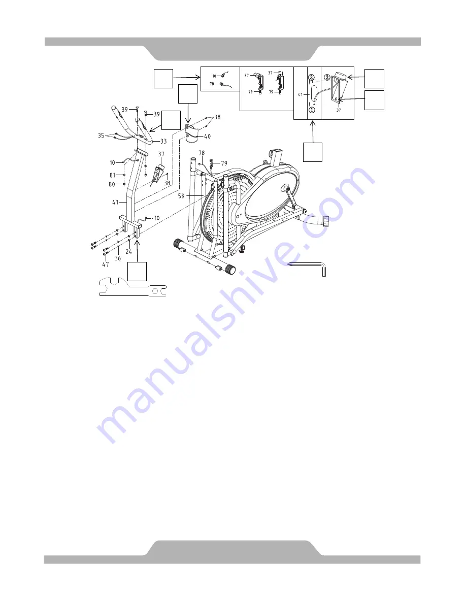
4. Hand Pulse Handlebar Support Frame, Tension Control Knob, Bottle Holder,
and Hand Pulse Handlebar Installation:
Step L:
Attach the Hand Pulse Handlebar Support Frame (41) onto the Mainframe
(59) with four Bolts (47), four Spring Washers (36), and four Washers (24). Using the
S6 Allen Wrench with Phillips Screwdriver, tighten the bolts until firm.
Step M:
Insert the Tension Cable (79) through the bottom hole of Hand Pulse
Handlebar Support Frame (41) and pull it out through the opening hole to connect with
the Tension Control Knob (37). See Figure D.
Step N:
Connect the Sensor Wire (78) coming out from the Mainframe (59) to the
Extension Sensor Wire (10) coming from the bottom of the Hand Pulse Handlebar
Support Frame (41). Make sure the connectors “click” when connected. See Figure
A.
Step O:
Turn the Tension Control Knob (37) to the lowest setting (counterclockwise).
Caution:
Do not continue to turn the Tension Control Knob (37) after reaching its
lowest or highest setting for it may damage the knob.
Put the cable end of resistance cable of Tension Control Knob (37) into the spring
hook of Tension Cable (79). See Figure B. Align the resistance cable of Tension
Control Knob (37) into the gap of metal bracket of Tension Cable (79) with the nuts
sitting above the metal bracket. Turn the tension control knob towards the highest
setting (clockwise) until the nuts are seated firmly on top of the metal bracket. See
Figure C. Tuck cable inside the Hand Pulse Handlebar Support Frame (41).
13
ASSEMBLY
Содержание Air Elliptical
Страница 4: ...3 LABEL PLACEMENT...
Страница 9: ...8 HARDWARE TOOLS PACK STEP 1 STEP 4 STEP 5 STEP 2 3 STEP 6...