background image

15

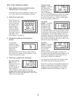
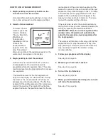
HOW TO USE THE MANUAL MODE

1. Begin pedaling or press any button on the

console to turn on the console.

A moment after you begin pedaling or press a but-

ton, a tone will sound, and the display will light.

2. Select the manual mode.

Each time you turn

on the console, the

manual mode will

be selected. If you

have selected a

workout, reselect

the manual mode

by pressing any of

the workout buttons

repeatedly until

zeros appear in the display.

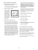
3. Change the resistance of the pedals as

desired.

As you pedal,

change the resis-

tance of the pedals

by pressing the

Resistance

increase and

decrease buttons. Note: After you press the but-

tons, it will take a moment for the pedals to reach

the selected resistance level.

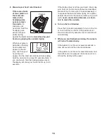
4. Follow your progress with the display.

The lower left dis-

play

—As you

exercise, the lower

left display can

show the elapsed

time and the dis-

tance (in miles or kilometers) that you have

pedaled. Note: When a workout is selected, the

display will show the time remaining in the workout

instead of the elapsed time.

The lower right

display

—The lower

right display can

show the your ped-

aling speed (in

miles or kilometers

per hour) and the approximate number of calories

that you have burned. The display also shows

your heart rate when you use the handgrip pulse

sensor (see step 5 on page 16).

The upper

display

—The upper

display can show

the elapsed time,

the distance that

you have pedaled,

your pedaling speed, and the approximate number

of calories you have burned. Press the Display but-

ton repeatedly until the upper display shows the

information that you are most interested in viewing.

Note: While information is shown in the upper dis-

play, the same information will not be shown in the

lower left or lower right display.
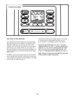
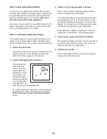
The lower

display

—The lower

display will show a

track representing

1/4 mile (402

meters). As you

exercise, indicators will appear in succession

around the track until the entire track appears. The

track will then disappear and the indicators will

again begin to appear in succession

To change the volume level of the console, press

the Volume increase and decrease buttons.

Note: The console can show pedaling speed and

distance in either miles or kilometers. To view or

change the unit of measurement, see HOW TO

CHANGE CONSOLE SETTINGS on page 19.

Содержание 785 F

Страница 1: ...erence QUESTIONS As a manufacturer we are commit ted to providing complete customer satisfaction If you have questions or if parts are damaged or missing DO NOT CONTACT THE STORE please contact Customer Care IMPORTANT You must note the product model number and serial number see the drawing above before contacting us CALL TOLL FREE 1 888 533 1333 Mon Fri 6 a m 6 p m MT Sat 8 a m 4 p m MT ON THE WEB...

Страница 2: ...XPLODED DRAWING 25 ORDERING REPLACEMENT PARTS Back Cover LIMITED WARRANTY Back Cover 2 WARNING DECAL PLACEMENT This drawing shows the location s of the warning decal s If a decal is missing or illegible see the front cover of this manual and request a free replacement decal Apply the decal in the location shown Note The decal s may not be shown at actual size PROFORM is a registered trademark of I...

Страница 3: ... 1 m of clearance in the front and rear of your ellipti cal exerciser and 2 ft 0 6 m on each side 5 Inspect and properly tighten all parts regu larly Replace any worn parts immediately 6 Keep children under age 12 and pets away from your elliptical exerciser at all times 7 Your elliptical exerciser should not be used by persons weighing more than 275 lbs 125 kg 8 Wear appropriate exercise clothes ...

Страница 4: ...his manual To help us assist you note the product model number and serial number before con tacting us The model number and the location of the serial number decal are shown on the front cover of this manual To avoid a registration fee for any service needed under warranty you must register the exercise cycle at www proformservice com registration Before reading further please familiarize yourself...

Страница 5: ...ser use the drawings below to identify small parts The number in parenthe ses below each drawing is the key number of the part from the PART LIST near the end of this manual The number following the parentheses is the quantity needed for assembly Note Some small parts may have been preassembled If a part is not in the hardware kit check to see if it has been preassembled M8 x 38mm Bolt 96 8 M8 Loc...

Страница 6: ... 83 83 82 82 82 3 While a second person holds the Upright 4 near the Frame 1 connect the Upper Wire Harness 110 to the Lower Wire Harness 111 Tip Avoid pinching the wires Slide the Upright 4 onto the Frame 1 Attach the Upright with four M8 x 19mm Patch Screws 82 and four M8 Split Washers 83 Do not tighten the Patch Screws yet 3 Avoid pinching the wires 1 82 82 82 83 83 4 110 111 To make assembly e...

Страница 7: ...Washer 98 to avoid breaking the Axle Cover do not over tighten the Patch Screw Repeat this step for the Left Roller Arm not shown Grease 20 55 66 98 53 82 59 5 Identify the Right Pedal Bracket 64 which is marked with a Right sticker Apply a small amount of grease to the inside of the tube on the Right Roller Arm 59 and to the barrel of an M10 x 60mm Bolt 100 Attach the Right Pedal Bracket 64 to th...

Страница 8: ...nal holes Repeat this step for the Left Handlebar not shown and the Left Handlebar Leg not shown 61 60 102 96 Hexagonal Holes 7 7 Apply a small amount of grease to the Pivot Axle 35 and to a 16mm Wave Washer 54 Insert the Pivot Axle 35 through the Upright 4 and then center it Slide the 16mm Wave Washer 54 an Inner Handlebar Cover 68 and the Right Handlebar Leg 60 onto the right side of the Pivot A...

Страница 9: ...Handlebar Leg 60 and to a 19mm Wave Washer 66 Identify the Right Pedal Arm 58 which is marked with a Right sticker and orient it as shown Slide the 19mm Wave Washer 66 and the Right Pedal Arm 58 onto the Right Handlebar Leg 60 Attach the Right Pedal Arm 58 with an M8 x 19mm Patch Screw 82 an Axle Cover 53 and an M8 x 25mm Washer 98 to avoid breaking the Axle Cover do not overtighten the Patch Scre...

Страница 10: ...ight Pulse Bar 9 Next pull the upper end of the wire tie upward out of the top of the Upright Then untie and discard the wire tie Slide the Right Pulse Bar 9 onto the right side of the Upright 4 Make sure that the hexago nal holes are in the indicated location Tip Avoid pinching the wires Attach the Right Pulse Bar 9 with two M8 x 38mm Bolts 96 and two M8 Locknuts 102 Make sure that the Locknuts a...

Страница 11: ... 19mm Patch Screws 82 7 63 110 104 4 Console Wire Pulse Wires Avoid pinching the wires 14 Plug the power adapter into the jack on the back of the console see HOW TO PLUG IN THE POWER ADAPTER on page 12 IMPORTANT If the elliptical exerciser has been exposed to cold temperatures allow it to warm to room temperature before plugging in the power adapter If you do not do this you may damage the console...

Страница 12: ...ert the bat teries into the battery compartment and then reattach the battery cover Make sure to orient the batteries as shown by the diagrams inside the battery com partment HOW TO MOVE THE ELLIPTICAL EXERCISER Due to the size and weight of the elliptical exerciser moving it requires two persons Stand in front of the elliptical exerciser hold the upright and place one foot against one of the fron...

Страница 13: ...al exerciser does not have a free wheel the pedals will continue to move until the flywheel stops When the pedals are stationary step off the higher pedal first Then step off the lower pedal HOW TO CHANGE THE INCLINE OF THE RAMP To vary the motion of the pedals you can change the incline of the ramp To change the incline press the latch button pull the ramp handle and raise or lower the ramp to th...

Страница 14: ...trainer workouts and six weight loss workouts Each workout automati cally changes the resistance of the pedals as it guides you through an effective workout You can even connect your MP3 player or CD player to the consoleʼs sound system and listen to your favorite music or audio books while you exercise To use the manual mode see page 15 To use a trainer workout see page 17 To use a weight loss wo...

Страница 15: ... display The lower right display can show the your ped aling speed in miles or kilometers per hour and the approximate number of calories that you have burned The display also shows your heart rate when you use the handgrip pulse sensor see step 5 on page 16 The upper display The upper display can show the elapsed time the distance that you have pedaled your pedaling speed and the approximate numb...

Страница 16: ...nds If the display does not show your heart rate make sure that your hands are positioned as described Be careful not to move your hands excessively or to squeeze the metal contacts tightly For optimal performance clean the metal contacts using a soft cloth never use alcohol abrasives or chemi cals to clean the contacts 6 Turn on the fan if desired Press the Fan button repeatedly to turn on the fa...

Страница 17: ...t The height of the flashing segment indicates the resistance level for the cur rent segment At the end of each segment of the workout a series of tones will sound and the next segment of the profile will begin to flash If a differ ent resistance level is programmed for the next segment the resistance level will appear in the display for a few seconds to alert you The resis tance of the pedals wil...

Страница 18: ...ext segment the resistance level will appear in the display for a few seconds to alert you The resis tance of the pedals will then change If the resistance level for the current segment is too high or too low you can manually override the setting by pressing the Resistance buttons IMPORTANT When the current segment of the workout ends the pedals will automatically adjust to the resistance level pr...

Страница 19: ...N option keeps the backlight on while the console is on The AUTO option keeps the backlight on only while you are pedaling The OFF option turns the backlight off The upper display will show the currently selected backlight option Press the Resistance increase button repeatedly to select the desired backlight option 3 Select a unit of measurement if desired The console can show pedaling speed and d...

Страница 20: ...n retighten the M10 x 22mm Bolt Reattach the right disc by rotating it clockwise into the right disc mount HOW TO ADJUST THE REED SWITCH If the console does not display correct feedback the reed switch should be adjusted To adjust the reed switch first use a flat screwdriver to rotate the left disc counterclockwise Then remove the left disc from the left disc mount Locate the Reed Switch 38 Loosen...

Страница 21: ...our goal is to strengthen your cardiovascular system you must perform aerobic exercise which is activity that requires large amounts of oxygen for prolonged periods of time For aerobic exercise adjust the intensity of your exercise until your heart rate is near the highest number in your training zone WORKOUT GUIDELINES Warming Up Start with 5 to 10 minutes of stretching and light exercise A warm ...

Страница 22: ...Achilles Stretch With one leg in front of the other reach forward and place your hands against a wall Keep your back leg straight and your back foot flat on the floor Bend your front leg lean forward and move your hips toward the wall Hold for 15 counts then relax Repeat 3 times for each leg To cause further stretching of the achilles tendons bend your back leg as well Stretches Calves achilles te...

Страница 23: ... 2 16mm Wave Washer 55 2 Crank Arm Spacer 56 2 Pedal Bracket Spacer 57 4 Pedal Arm Bushing 58 1 Right Pedal Arm 59 1 Right Roller Arm 60 1 Right Handlebar Leg 61 1 Right Handlebar 62 2 Handlebar Cap 63 2 Pulse Sensor Assembly 64 1 Right Pedal Bracket 65 6 M6 x 25mm Flat Head Screw 66 4 19mm Wave Washer 67 2 Outer Handlebar Cover 68 2 Inner Handlebar Cover 69 2 M4 x 16mm Reed Switch Screw 70 2 Inne...

Страница 24: ...Wire Harness 111 1 Lower Wire Harness 112 1 Power Adapter 113 1 Drive Belt 114 2 Foam Grip 115 1 Right Pedal 116 1 Right Pedal Insert 117 2 Pulse Wire 118 2 Upper Bushing Assembly Tool Grease Packet Userʼs Manual Key No Qty Description Key No Qty Description Note Specifications are subject to change without notice See the back cover of this manual for information about ordering replacement parts T...

Страница 25: ...25 26 27 28 29 30 30 31 32 32 33 34 34 35 36 36 37 38 39 40 40 42 42 41 41 43 43 63 63 78 78 79 80 81 81 82 82 82 82 82 82 83 83 83 83 83 83 84 85 85 86 86 87 88 89 90 91 91 93 93 94 96 96 97 98 97 98 108 109 108 109 102 102 102 102 102 102 92 102 103 21 21 21 21 5 21 21 106 69 104 104 104 39 69 111 110 112 113 117 ...

Страница 26: ... 98 53 53 40 40 55 36 56 57 57 62 66 67 68 70 118 71 72 73 75 76 76 76 77 96 97 97 101 53 82 97 98 82 82 98 99 100 92 102 104 104 104 104 65 65 65 108 108 105 54 66 42 95 107 107 114 105 EXPLODED DRAWING B Model No PFEL57908 1 R0509A ...

Страница 27: ...55 36 56 57 57 58 59 60 61 62 116 115 64 66 67 68 118 70 71 72 74 77 96 99 100 97 101 97 82 98 97 98 82 82 98 95 102 104 104 104 104 65 65 65 105 105 108 108 54 66 42 92 107 107 114 EXPLODED DRAWING C Model No PFEL57908 1 R0509A ...

Страница 28: ...ty the customer will be responsible for a minimal handling charge For in home service the customer will be responsible for a minimal trip charge This warranty does not extend to any damage to a product caused by or attributable to freight damage abuse misuse improper or abnormal usage or repairs not provided by an ICON authorized service center products used for commercial or rental purposes or pr...

Отзывы: