21
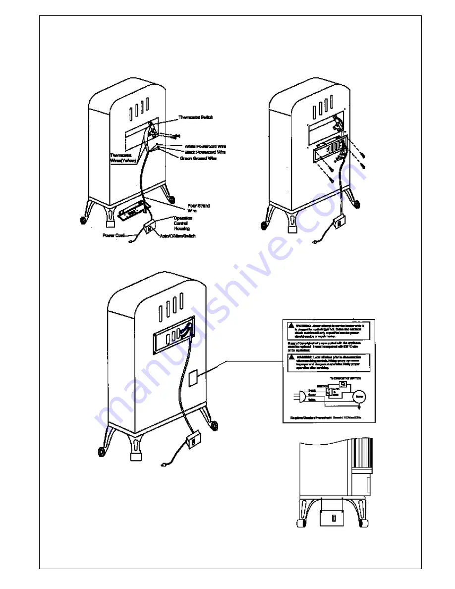
INSTALLING BLOWER ACCESSORY
BLOWER ACCESSORY MODEL NFHTX186
Figure 4-A Routing Power Cord
Figure 4-B Routing Power Cord
WiringDiagram Decal
Figure 5 Mounting Control Housing
SIDE VIEW
Страница 1: ...ENTED ROOM HEATERS Water vaporis a by product of gas combustion An unvented room heater productes approximately one 1 ounce 30ml of water for every 1 000 BTU s 3KW s of gas input per hour Refer to pag...
Страница 2: ...e Propane LP supply tank s indoors 3 If you smell gas Shut off gas supply Do not try to light any appliance Do not touch any electrical switch do not use any phone in your building Immediately call yo...
Страница 3: ...ee operation State and local codes in some areas prohibit the use of vent free heaters UNPACKING 1 Remove top inner pack 2 Tilt carton so that fireplace is upright 3 Remove protective side packaging 4...
Страница 4: ...ing if You Have a Confined or Unconfined Space Use this worksheet to determine if you have a confined or unconfined space Space Includes the room in which you will install heater plus any adjoining ro...
Страница 5: ...oom unconfined Figure 2 Ventilation Air from Inside Building Example Gas water heater 30 000 Btu Hr Vent free heater 26 000 Btu Hr Total 56 000 Btu Hr WARNING If the area in which the heater may be op...
Страница 6: ...late If your gas supply can not meet that requirement do not install heater Call dealer where you bought heater from for proper heater type Figure 4 Minimum Clearance to Wall CLEARANCES TO COMBUSTIBLE...
Страница 7: ...gas is commonly known as wellhead gas CAUTION Only use a new black iron or steel pipe Internally tinned cop per tubing may be used in certain areas Check your local codes Use pipe of 1 2 diameter or g...
Страница 8: ...ure of liquid soap and water to gas joints Bubbles forming show a leak 5 Correct all leaks immediately 6 Reconnect heater and equipment shutoff valve to gas supply Check reconnected fittings for leaks...
Страница 9: ...chnician to inspect the appliance and to replace any part of the control system and any gas control which has been under water LIGHTING INSTRUCTIONS 1 STOP Read the safety informatuion above 2 Set the...
Страница 10: ...55 F 12 78 C If no heat is desired turn the gas cntrol knob to the PILOT position Main Burner Operation Description of Gas Control Knob OFF position PILOT position LO HI will allow the hydraulic ther...
Страница 11: ...pas sageways of heater clean Inspect these areas of heater before each use Have heater inspected yearly by a qualified service person Heater may need more frequent cleaning due to excessive lint from...
Страница 12: ...Pilot flame not touching thermocouple This allows thermocouple to cool causing the pilot flame to go out This problem could be caused by one or both of the following A Low gas pressure B Dirty or part...
Страница 13: ...n logs or inside of fireplace 1 Improper log placement 2 Air holes at burner inlet are blocked 3 Burner flame holes are blocked 1 Properly locate logs see Installing Logs page 9 2 Clean out air holes...
Страница 14: ...o return the defective part to the factory Warranty card PARTS NOT UNDER WARRANTY Contact authorized dealers of this prod uct or Parts Central If they can t supply original replacement part s call PRO...
Страница 15: ...ngle iron Figure 3 Insert the pinhole on the upper part of log 4 into the pin on the left side of log 1 Place the lower part on the flat roof at the left side of log 3 Figure 4 Insert the pinhole on t...
Страница 16: ...16 ILLUSTRATED PARTS BREAKDOWN SN250TYLA D SL250TYLA D...
Страница 17: ...0 4 2 0 L E G N r o t c e j n I 1 8 0 1 0 5 2 0 L E P L r o t c e j n I 1 9 0 0 0 0 7 3 B E y l b m e s s A e b u T t e l t u O 1 1 0 1 3 1 F 1 8 V R N G N 3 I F 1 8 V R r o t a l u g e R 1 1 1 8 1 F...
Страница 18: ...18 ILLUSTRATED PARTS BREAKDOWN SN250TYLA D SL250TYLA D 20...
Страница 19: ...1 0 0 L S n m u l o C t h g i R 1 1 8 1 0 1 1 0 L E e r i W g n i t a r o c e D r e p p U 1 1 9 4 0 3 0 2 0 0 L S r e v u o L d i M r e p p U 2 2 0 1 6 0 6 0 0 L E r o t c e l f e R e d i S 2 2 1 1 1...
Страница 20: ...thread that previously bond the electrical wire to collect and pack the outside connection wire of the cable 6 Place operation control housing at the bottom of stove Use two black screws provided in b...
Страница 21: ...21 INSTALLING BLOWER ACCESSORY BLOWER ACCESSORY MODEL NFHTX186 Figure 4 A Routing Power Cord Figure 4 B Routing Power Cord Wiring Diagram Decal Figure 5 Mounting Control Housing SIDE VIEW...