background image

20

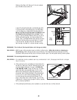
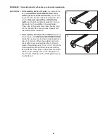
Remove the three 3/4" Screws (10) and carefully

pivot the Motor Hood (57) off.

Locate the Reed Switch (64) and the Magnet (42)

on the left side of the Pulley (43). Turn the Pulley

until the Magnet is aligned with the Reed Switch.

Make sure that the gap between the Magnet and

the Reed Switch is about 1/8 in. (3 mm).

If nec-

essary, loosen the Reed Switch Screw (12), move

the Reed Switch slightly, and then retighten the

Screw. Then, reattach the Motor Hood (not shown).

Reattach the Hood Screws (not shown), if neces-

sary. Raise the Uprights. Run the treadmill for a

few minutes to check for a correct speed reading.

PROBLEM: The incline of the treadmill does not change correctly

SOLUTION:

a. With the key in the console, press one of the Incline buttons.

While the incline is changing, re-

move the key.

After a few seconds, re-insert the key. The treadmill will automatically rise to the

maximum incline level and then return to the minimum level. This will recalibrate the incline system.

PROBLEM: The walking belt slows when walked on

SOLUTION:

a. If an extension cord is needed, use only a 3-conductor, 1 mm

2

(14-gauge) cord that is no longer

than 1.5 m (5 ft.).

b. If the walking belt is overtightened, treadmill perfor-

mance may decrease and the walking belt may be-

come damaged. Remove the key and

UNPLUG

THE POWER CORD.

Using the hex key, turn both

idler roller bolts counterclockwise, 1/4 of a turn.

When the walking belt is properly tightened, you

should be able to lift each edge of the walking belt

2 to 3 in. (5 to 7 cm) off the walking platform. Be

careful to keep the walking belt centered. Then,

plug in the power cord, insert the key, and run the

treadmill for a few minutes. Repeat until the walking

belt is properly tightened.

c. If the walking belt still slows when walked on, see the front cover of this manual.

Top

View

42

12

64

1/8 in.

43

Idler Roller Bolts

2–3 in.

b

57

10

Содержание 1095 ZLT PETL71709.0

Страница 1: ...equipment Save this manual for future reference USERʼS MANUAL QUESTIONS If you have questions or if there are missing parts please contact us Call 08457 089 009 From Ireland 053 92 36102 E mail www iconsupport eu Write ICON Health Fitness Ltd c o HI Group PLC Express Way Whitwood West Yorkshire WF10 5QJ UK In Australia Please contact the store where you purchased this product www iconeurope com ...

Страница 2: ...DRAWING 24 ORDERING REPLACEMENT PARTS Back Cover RECYCLING INFORMATION Back Cover 2 This drawing shows the locations of the warning decals If a decal is missing or illegible call the telephone number on the front cover of this manual and request a free replacement decal Apply the decal in the location shown Note The decals may not be shown at actual size WARNING DECAL PLACEMENT PROFORM is a regist...

Страница 3: ...hen replacing the fuse in the power cord adapter insert an ASTA approved BS1362 13 amp fuse into the fuse carrier 12 If an extension cord is needed use only a 3 conductor 1 mm2 14 gauge cord that is no longer than 1 5 m 13 Keep the power cord away from heated sur faces 14 Never move the walking belt while the power is turned off Do not operate the treadmill if the power cord or plug is damaged or ...

Страница 4: ...ys unplug the power cord immediately after use before cleaning the treadmill and before performing the mainte nance and adjustment procedures described in this manual Never remove the motor hood un less instructed to do so by an authorized ser vice representative Servicing other than the procedures in this manual should be performed by an authorized service representative only 25 This treadmill is...

Страница 5: ...he treadmill If you have questions after read ing this manual please see the front cover of this man ual To help us assist you note the product model number and serial number before contacting us The model number and the location of the serial number decal are shown on the front cover of this manual Before reading further please familiarize yourself with the parts that are labeled in the drawing b...

Страница 6: ...w to identify the assembly hardware The number in parentheses below each drawing is the key number of the part from the PART LIST near the end of this manual The number after the parentheses is the quantity needed for assembly Note If a part is not in the hardware kit check to see if it is preattached to one of the parts to be assembled To avoid damaging plastic parts do not use power tools for as...

Страница 7: ... Nut 8 that you removed in step 1 Do not overtighten the Nut the Base Wheel must turn freely 4 8 3 81 80 78 72 74 78 4 Wire Tie 72 78 Wire Tie 2 With the help of a second person carefully tip the treadmill onto its left side Partially fold the Frame 53 so that the treadmill is more stable do not fully fold the Frame yet Remove and discard the two indicated bolts A and the shipping bracket B Cut th...

Страница 8: ...tep with a sec ond Bolt Spacer 3 3 8 x 4 Bolt 6 and 3 8 Star Washer 9 Orient the Left Upright 71 and the Left Upright Spacer 73 as shown Hold the Left Upright Spacer and the Left Upright against the Base 80 Tighten the 3 8 x 4 Bolts 6 until the heads of the Bolts touch the Left Upright do not fully tighten the Bolts yet Press a Base Cap 75 into the Base 80 With the help of a second person tip the ...

Страница 9: ...pright 72 Connect the Upright Wire 78 to the console wire See the inset drawing The connectors should slide together easily and snap into place If they do not turn one connector and try again IF THE CONNECTORS ARE NOT CON NECTED PROPERLY THE CONSOLE MAY BE DAMAGED WHEN THE POWER IS TURNED ON Remove the wire tie from the Upright Wire Then insert the connectors into the Right Upright 72 Set the cons...

Страница 10: ...54 are in the posi tions shown Attach the Latch Bracket 68 to the bracket on the Base 80 with two 3 8 x 2 Bolts 4 and two 3 8 Nuts 8 Attach the upper end of the Latch Assembly 55 to the bracket on the Frame 53 with a 3 8 x 2 Bolt 4 and a 3 8 Nut 8 Note It may be nec essary to move the Frame back and forth to align the Latch Assembly with the bracket Lower the Frame 53 see HOW TO LOWER THE TREADMIL...

Страница 11: ...with a power cord having an equipment earthing conductor and an earthing plug IMPORTANT If the power cord is damaged it must be replaced with a manufacturer recommended power cord See drawing 1 Plug the indicated end of the power cord into the socket on the treadmill HOW TO PLUG IN THE POWER CORD IN AUSTRALIA See drawing 2 Plug the power cord into an appropriate outlet that is properly installed a...

Страница 12: ...through an effec tive exercise session To turn on the power see page 13 To use the man ual mode see page 13 To use a preset workout see page 15 To use the information mode see page 16 IMPORTANT If there is a sheet of clear plastic on the face of the console remove the plastic To pre vent damage to the walking platform wear clean athletic shoes while using the treadmill The first time you use the t...

Страница 13: ...alking belt To start the walking belt press the Start button the Go button the Speed increase button or one of the speed buttons numbered 4 through 20 If you press the Start button the Go button or the Speed increase button the walking belt will begin to move at 2 km h As you exercise change the speed of the walking belt as desired by pressing the Speed increase and decrease buttons Each time you ...

Страница 14: ...n the optional chest pulse sensor see page 16 Before using the handgrip pulse sensor first re move the sheets of clear plastic from the metal contacts on the pulse bar In ad dition make sure that your hands are clean To use the handgrip pulse sensor stand on the foot rails and hold the pulse bar with your palms on the metal contacts Avoid moving your hands When your pulse is detected two dashes wi...

Страница 15: ... of the flash ing segment indicates the speed setting for the current segment At the end of each segment a series of tones will sound and the next segment of the profile will begin to flash If a different speed and or incline settings is programmed for the next segment the speed and or incline settings will flash in the display to alert you The treadmill will automatically adjust to the new speed ...

Страница 16: ...eaker to the reset position and insert the key into the console However when you remove the key the displays will remain lit although the buttons will not function If the demo mode is turned on a d will ap pear in the speed display while the information mode is selected To turn on or turn off the demo mode press the Speed decrease button To exit the information mode remove the key from the console...

Страница 17: ...ob is locked in the storage position To protect the floor or carpet from damage place a mat under the treadmill Keep the treadmill out of di rect sunlight Do not leave the treadmill in the storage position in temperatures above 85 F 30 C HOW TO MOVE THE TREADMILL Before moving the treadmill convert the treadmill to the stor age position as described above Make sure that the latch knob is locked in...

Страница 18: ...may be nec essary to push the frame forward as you pull the knob to the left Pivot the frame downward and release the latch knob 2 Hold the metal frame firmly with both hands and lower it to the floor CAUTION Do not grip only the plastic foot rails or drop the frame to the floor Bend your legs and keep your back straight Latch Knob Frame Frame ...

Страница 19: ...minutes and then press the switch back in b Make sure that the power cord is plugged in If the power cord is plugged in unplug it wait for five minutes and then plug it back in c Remove the key from the console Reinsert the key into the console d If the treadmill still will not run please see the front cover of this manual PROBLEM The console displays remain lit when you remove the key from the co...

Страница 20: ...treadmill will automatically rise to the maximum incline level and then return to the minimum level This will recalibrate the incline system PROBLEM The walking belt slows when walked on SOLUTION a If an extension cord is needed use only a 3 conductor 1 mm2 14 gauge cord that is no longer than 1 5 m 5 ft b If the walking belt is overtightened treadmill perfor mance may decrease and the walking bel...

Страница 21: ... in the power cord insert the key and run the treadmill for a few minutes Repeat until the walking belt is centered b If the walking belt slips when walked on first re move the key and UNPLUG THE POWER CORD Using the hex key turn both idler roller bolts clock wise 1 4 of a turn When the walking belt is cor rectly tightened you should be able to lift each side of the walking belt 2 to 3 in 5 to 7 c...

Страница 22: ...your goal is to strengthen your cardiovascular system you must perform aerobic exer cise which is activity that requires large amounts of oxygen for prolonged periods of time For aerobic ex ercise adjust the intensity of your exercise until your heart rate is near the highest number in your training zone WORKOUT GUIDELINES Warming Up Start with 5 to 10 minutes of stretching and light exercise A wa...

Страница 23: ... 1 Hex Key 52 1 Right Rear Foot 53 1 Frame 54 1 Latch Knob 55 1 Storage Latch 56 4 1 Tek Screw 57 1 Motor Hood 58 1 Lift Frame Ground Wire 59 1 Drive Motor Isolator 60 1 Drive Motor 61 1 Lift Frame 62 2 Drive Motor Bushings 63 1 Rear Roller Ground Wire 64 1 Reed Switch 65 1 Reed Switch Clamp 66 1 Belly Pan 67 1 Reset Off Circuit Breaker 68 1 Latch Bracket 69 1 Power Cord 70 1 Controller 71 1 Left ...

Страница 24: ...13 14 14 16 16 20 20 21 21 21 21 21 21 26 26 27 27 28 28 33 33 35 35 35 2 2 21 21 36 37 38 39 44 42 36 43 45 47 46 39 40 41 49 48 50 52 54 55 40 38 53 49 51 95 103 24 EXPLODED DRAWING A Model No PETL71709 0 R0110A ...

Страница 25: ...12 20 20 34 34 34 2 2 2 2 57 58 63 69 64 65 66 67 10 10 10 11 1 70 15 15 22 60 59 61 101 32 98 20 29 20 20 20 29 24 23 99 62 30 100 EXPLODED DRAWING B Model No PETL71709 0 R0110A 25 ...

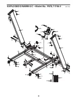
Страница 26: ...68 56 56 56 5 5 7 6 6 6 6 7 9 9 17 18 19 19 4 4 8 8 8 8 31 31 71 73 75 5 7 5 7 77 72 81 80 79 79 79 74 81 75 83 82 78 78 76 76 25 56 79 25 9 3 3 3 97 96 104 26 EXPLODED DRAWING C Model No PETL71709 0 R0110A ...

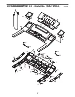
Страница 27: ...1 10 10 10 10 10 10 10 10 10 10 10 20 86 89 85 84 87 92 94 93 91 88 90 10 10 10 1 1 1 1 10 102 27 EXPLODED DRAWING D Model No PETL71709 0 R0110A ...

Страница 28: ...s see the PART LIST and the EXPLODED DRAWING near the end of this manual RECYCLING INFORMATION This electronic product must not be disposed of in municipal waste To pre serve the environment this product must be recycled after its useful life as re quired by law Please use recycling facilities that are authorized to collect this type of waste in your area In doing so you will help to conserve natu...

Отзывы: