


3. Monitor Settings
Not all video controllers produce exactly the same video output levels or the same timing. The
following procedure can be used to select the desired video mode as well as optimize your
monitor’s image quality. When adjusting your monitor, the use of video test software such as
DisplayMate for Windows by SONERA Technologies can be very beneficial.
The SXT2011 automatically adjusts to most incoming video signals. Usually, only brightness,
contrast and phase need to be adjusted by the user. “On Screen Programming” helps make
setup and adjustment of these settings easy. The menus are selected and the menu items are
adjusted using the buttons located on the monitor’s front panel. These buttons are enabled or
disabled by a rocker switch labeled “SET UP” located on the side of the monitor. This feature is
provided to inhibit tampering once the monitor is in actual use. Turn the SET UP switch to the
‘On’ position to enable set up and adjustment. If you are using a “Plug and Play” operating
system adjust your desktop display settings to the following before connecting the SXT2011 to
your computer:
Vertical Refresh:
60 Hz
Resolution:
1280 x 1024
If you are using a “Plug and Play” operating system, the monitor type and default settings are
automatically detected by the operating system. If you are not using “Plug and Play”, set your
monitor type to:
Manufacture:
(Standard monitor type)
Model:
Super VGA 1290 x 1024 @ 60 Hz
Vertical Refresh:
60 Hz
Resolution:
1280 x 1024
Once the monitor is powered up, press the
menu
button. After the On Screen Display (OSD)
menu appears select the “Brightness and Contrast” function by continuing to depress the menu
button until it’s graphic is highlighted.
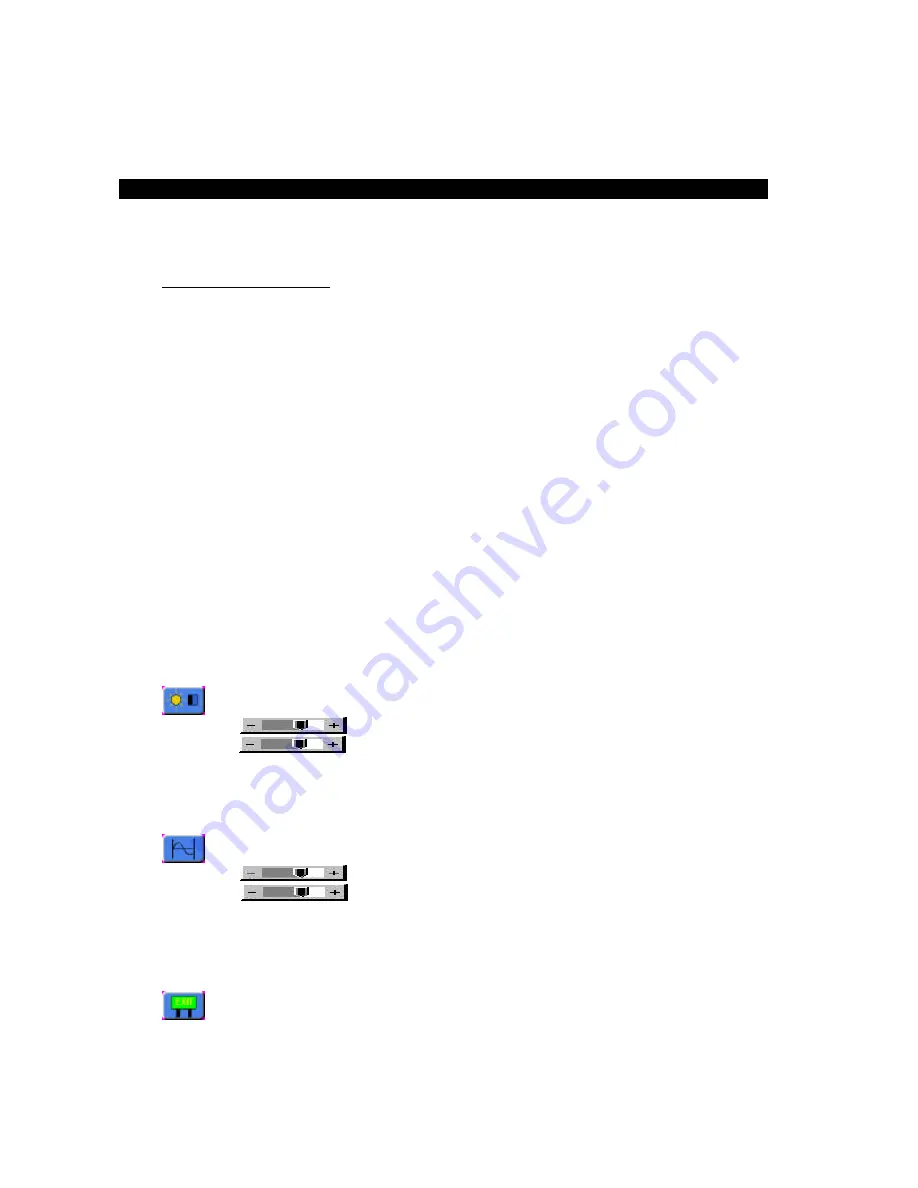
Once this graphic is highlighted, the following image will appear:
Brightness
Increase/decrease panel brightness level, total: 100 steps
Contrast
Increase/decrease panel contrast level, total: 100 steps
Use the
⇑
and
⇓
buttons to select either contrast or brightness. Now use
⇐
and
⇒
buttons to set
the desired level. Once brightness and contrast have been set the phase should be adjusted.
Continue pressing the
menu
button until “Frequency and Phase” graphic is highlighted.
Once this graphic is highlighted, the following image will appear:
Frequency
Adjust the image horizontal size
Phase
Fine-tune the data sampling position (adjust image quality)
Use the
⇑
and
⇓
buttons to select phase. Now use
⇐
and
⇒
buttons to fine-tune the image
quality. After completing this adjustment, exit the set up menu by either waiting about five
seconds without further button depressions or by hitting the
menu
button and scrolling until the
Exit graphic is highlighted.
Once the following graphic is highlighted press the
⇒
to exit.
3-1
Mode and Image Adjustment


