8
–
PRM 125
5. INSTALLATION
5.1 General
Drive is transmitted from the engine to the gearbox via a flexible centre drive plate (damper plate) which bolts to the
engine flywheel, the gearbox input shaft is driven from the centre spline.
These drive plates have a degree of torsional flexibility, the purpose being to reduce engine torsional or cyclic vibrations
and prevent them being passed to the transmission.
The strongest engine vibrations are usually those caused by firing in the cylinders; diesel engines which have high
compression ratios, usually generate stronger vibration pulses than petrol (gasoline) engines; and it is often the case
that of two engines of roughly equivalent size, the one having the greater number of cylinders will tend to run more
smoothly than the one with fewer cylinders, although this is by no means always the case.
In all marine installations, correct alignment of the engine, gearbox and propeller shaft is extremely important
–
misalignment can cause noise, vibration and premature failure
– and it is strongly recommended that all the procedures
detailed in this manual are carefully followed.
CAUTION:
It is particularly important to ensure the torsional compatibility of the complete
propulsion system from engine through to propeller since disregarding this may result in gear
noise at low speed operation and in extreme cases damage or failure of components. PRM Newage
Ltd. will provide all possible information and assistance to help find solutions to potential torsional
problems, but it is the ultimate responsibility of the person assembling the drive and driven
equipment to ensure that they are torsionally compatible.
5.2 Checking the engine Flywheel Housing
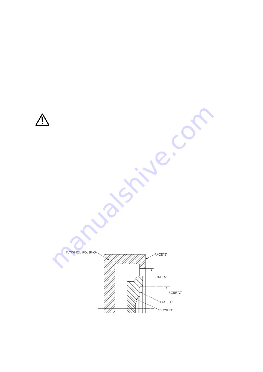
Attach a dial test indicator, calibrated in units of 0.025mm (0.001in.) or smaller, to the flywheel so that the measuring
stylus of the indicator is perpendicular to the bore of the flywheel housing (bore A on Fig.2). Rotate the flywheel and
check the deviation on the indicator over one complete revolution; this should not exceed 0.152mm (0.006in.) total
indicator reading.
With the dial test indicator still attached to the flywheel, re-position the stylus so that it is perpendicular to the face of the
flywheel housing (face B on Fig. 2), Rotate the flywheel and check the deviation over one complete revolution; again,
this should not exceed 0.152mm (0.006in.) total indicator reading.
5.3 Checking the Engine Flywheel
Attach a dial test indicator, calibrated to 0.025mm (0.001in.) or less, to the engine flywheel housing so that the
measuring stylus of the indicator is perpendicular to the bore of the register in the flywheel (bore C on Fig. 3). Rotate the
flywheel through one complete revolution and note the deviation, this should not exceed 0.125mm (0.005in.) total
indicator reading.
With the dial test indicator still attached to the flywheel housing, reposition the stylus so that it is perpendicular to the
face of the flywheel register (D on Fig. 3). Rotate the flywheel through one complete revolution and note the deviation,
this should not exceed 0.125mm (0.005in.) total indicator reading.
Figure 3 - Checking the Flywheel and Flywheel Housing
Содержание PRM 125
Страница 1: ...PRM 125 WORKSHOP MANUAL...
Страница 2: ......
Страница 11: ...9 PRM 125 BASIC INSTALLATION DETAILS PRM 125 Figure 4 Intallation Details...
Страница 23: ...21 PRM 125 13 Exploded view and Cross section Figure 5 Exploded view and cross section...
Страница 24: ...22 PRM 125...
Страница 25: ...23 PRM 125...
Страница 26: ...24 PRM 125...
Страница 28: ...26 PRM 125 NOTES...


