


516514
49
Section 5 Service Procedures
To reduce the risk of electric shock, fire, explosion, serious injury or death:
• Disconnect electric power to the dryer(s) before servicing.
• Close gas shut-off valve to gas dryer(s) before servicing.
• Never start the dryer(s) with any guards/panels removed.
• Whenever ground wires are removed during servicing, these ground wires must be
reconnected to ensure that the dryer is properly grounded.
W001R1
WARNING
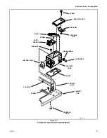
37. FRONT PANEL AND PANEL SEAL
a. While supporting the access panel, remove two
screws from bottom edge of access panel. Refer
to Figure 7.
b. Gently lower the access panel to disengage
locators from bottom edge of front panel. Refer
to Figure 37.
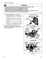
c. Remove two screws holding bottom tabs on
front panel to dryer side panels. Swing bottom
of front panel away from dryer far enough to
disengage hold-down clips and locators from
cabinet top.
d. Disconnect wires from door switch.
NOTE: Refer to wiring diagram when rewiring
switch.
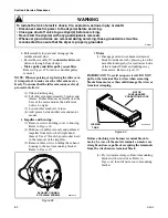
e. Remove front panel seal from flange around
inside of door opening.
NOTE: Be sure seal is properly positioned when
installing on front panel.
Figure 36
38. DOOR SWITCH
a. While supporting the access panel, remove two
screws from bottom edge of access panel. Refer
to Figure 7.
b. Gently lower the access panel to disengage
locators from bottom edge of front panel. Refer
to Figure 37.
c. Remove two screws holding tabs on front panel
to dryer side panels. Swing bottom of front
panel away from dryer far enough to disengage
hold-down clips and locators from cabinet top.
d. Disconnect wires from door switch. Refer to
NOTE: Refer to wiring diagram when rewiring
switch.
e. Depress tabs on switch and push out of front
panel. Refer to Figure 36.
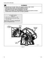
39. DOOR CATCH
a. While supporting the access panel, remove two
screws from bottom edge of access panel. Refer
to Figure 7.
b. Gently lower the access panel to disengage
locators from bottom edge of front panel. Refer
to Figure 37.
c. Remove two screws holding bottom tabs on
front panel to dryer side panels. Swing bottom
of front panel away from dryer far enough to
disengage hold-down clips and locators from
cabinet top.
d. Disconnect wires from door switch.
NOTE: Refer to wiring diagram when rewiring
switch.
e. Depress tabs on top and bottom of catch and
push out of front panel.
DOOR
SWITCH
TABS
D240SE3A
To Test Door Switch
1. Set meter to read Ohms and apply meter probes
on switch terminals 1 and 3 with door closed.
You should get “zero” reading.
2. Apply probes to terminals 1 and 2 with door
closed. The meter should read “infinite”.
3. Open door. Meter should read “infinite”
between 1 and 3 and “zero” between 1 and 2.
Содержание DAM 9
Страница 1: ...DAM 9 SERVICE MANUAL INDUSTRIAL DRYERS PUBLICATION DATE 02 01 516514 ...
Страница 2: ......
Страница 24: ...22 516514 Section 4 Grounding Copyright Alliance Laundry Systems LLC DO NOT COPY or TRANSMIT Notes ...
Страница 90: ...88 516514 Section 6 Adjustments Copyright Alliance Laundry Systems LLC DO NOT COPY or TRANSMIT Notes ...
Страница 126: ...124 516514 Section 8 Wiring Diagrams Copyright Alliance Laundry Systems LLC DO NOT COPY or TRANSMIT Notes ...
Страница 127: ......
Страница 128: ......