background image

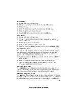
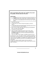
Factory Alarm Disarm (-) Output
The GRAY/WHITE wire will provide a 0.75 second ground output when the
START button is pressed.
1. Arm the vehicle factory alarm system.

2. Use a volt/ohmmeter to locate the one wire that will show ground only

when the driver door key cylinder is held in the unlock position.
NOTE: most factory alarm disarm wires will show 8-12 volts while
armed. A few vehicle disarm wires will rest at a neutral state while
armed. Regardless of type, both types will change to ground when the
key cylinder is turned to unlock.

3. Connect the GRAY/WHITE wire to the factory alarm disarm wire.

Accessory Remote Start (-) Input
The BLUE/ORANGE wire will accept a (-) input pulse to activate the
remote start.

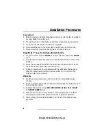
Trunk Switch
1. Locate the vehicle trunk switch that shows ground when the trunk is

open only.

2. Connect the alarm module TAN/BLACK wire to the vehicle trunk switch

wire.

3. If the vehicle does not have a trunk switch, install a pin switch and

connect it to the alarm module TAN/BLACK wire.

Ignition Switch Connections
NOTE: Because these wires can draw high current, we recommend that they
be soldered and shrink tubed or taped. If only one PINK wire is needed, tape
the end of the second PINK wire to prevent a short circuit. The main control
module has an 18 ga PINK wire that must be connected to the vehicle
ignition wire with one of the satellite module 14 ga wires.

Ignition #1 Ignition #2
The satellite relay module has two onboard 30-amp relays. Most vehicles have 
only one ignition wire necessary to start the vehicle. Some vehicles have two
ignition wires. Make all wire connections at the ignition switch wire harness.

(Con tin ued on next page)

12

PrimeStart 650 Installation Manual

Содержание PrimeStart 650

Страница 1: ...PrimeStart 650 Installation Manual...

Страница 2: ...PrimeStart 650 Installation Manual...

Страница 3: ...erse Light 10 Interior Light Illumination 11 Channel 2 Accessory Output Trunk Release 11 Channel 6 Accessory Output 11 Channel 9 Accessory Output 11 Remote Start Armed Signal Output 11 Factory Alarm D...

Страница 4: ...ttery 4 Keep extensions as short as possible Use same gauge wires for short extensions and larger gauge wires for longer extensions 5 Before installing discuss the placement of the LED indicator and v...

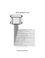
Страница 5: ...3 PrimeStart 650 Installation Manual Main Wiring Diagram 16 Pin...

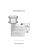
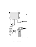
Страница 6: ...Main Wiring Diagram 12 Pin 4 PrimeStart 650 Installation Manual...

Страница 7: ...5 PrimeStart 650 Installation Manual Satellite Relay Module Diagram...

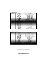
Страница 8: ...de 12 GREEN WHITE Unlock Motor Side 13 GREEN RED Unlock Polarity or Select 14 BLUE BLACK Lock Switch Side 15 BLUE WHITE Lock Motor Side 16 BLUE RED Lock Polarity or Select 12 Pin Connector Pin Number...

Страница 9: ...r Wire Color Description 1 YELLOW Starter Interrupt Switch Side 2 GRAY Heater AC Output 3 VIOLET Starter Interrupt Starter Side 4 PINK Ignition Output 5 RED Battery 6 PINK Ignition Output 7 PrimeStart...

Страница 10: ...3 Route the antenna cable behind the driver side windshield pillar above the headliner and behind the rear view mirror 4 Fasten the antenna to the windshield with the attached adhesive tape Attach th...

Страница 11: ...steering column housing or steering column support bracket DO NOT mount the sensor near moving parts or in the direct path of an air duct opening 1 Plug the impact sensor BLUE 4 pin connector into th...

Страница 12: ...the parking lights are positive trigger connect the RED WHITE wire to the battery positive terminal through the 20 amp fuse assembly NOTE Do not connect the RED WHITE wire to the control unit RED wir...

Страница 13: ...re pressed at the same time for 1 2 seconds If the ARM DISARM and SILENT buttons are continually pressed the output will stay at ground as long as the buttons are held This output can be used for opti...

Страница 14: ...k switch that shows ground when the trunk is open only 2 Connect the alarm module TAN BLACK wire to the vehicle trunk switch wire 3 If the vehicle does not have a trunk switch install a pin switch and...

Страница 15: ...12 volts when the ignition key is in the ON position 0 volts while the starter is cranking and 12 volts while running 2 Cut this wire in half Start the vehicle and turn the blower switch on The blower...

Страница 16: ...ned Some vehicles combine the neutral safety switch and the steering column shift mechanism together The starter wires run from the combined switch directly to the starter solenoid The remote start wi...

Страница 17: ...r engages 5 Activate the remote engine starter 6 If the vehicle starter engages immediately press the brake pedal to disengage shut down the remote start You have a combined type neutral safety switch...

Страница 18: ...16 PrimeStart 650 Installation Manual General Motors Sport Utility Vehicles Trucks and Column Shift Passenger Vehicles Dodge Dakota Pickup Trucks...

Страница 19: ...llation Manual Door Lock Unlock The system has onboard door lock relays to lock and unlock all of the doors as well as a two stage unlock The diagrams on pages 17 20 will illustrate standard lock unlo...

Страница 20: ...18 PrimeStart 650 Installation Manual...

Страница 21: ...19 PrimeStart 650 Installation Manual...

Страница 22: ...20 PrimeStart 650 Installation Manual...

Страница 23: ...5 volts AC while the vehicle is idle and increase an additional 1 to 5 volts AC when the engine RPM is raised to 3000 4000 RPM 3 Connect the WHITE LIGHT GREEN wire to the vehicle tach wire Hood Switch...

Страница 24: ...HITE wire to one end of the other supplied 20 amp fuse assembly 3 Connect the BLACK wire to the 10 mm ring terminal 4 Connect the 10 ga RED wire to one end of both 30 amp fuse assemblies 5 Connect the...

Страница 25: ...RPM 2 Turn the ignition key OFF 3 Start the engine with the ignition key 4 Within 10 seconds of starting the vehicle begin flicking the valet switch on then off 15 times counting the siren chirps NOTE...

Страница 26: ...e LED on solid red 2 Select the feature you wish to program from the Programming Table for System Features or the Programming Table for Remote Controls on pages 25 26 Note the number of chirps associa...

Страница 27: ...ds the siren will chirp once for OFF twice for ON Programmable 0 or 3 Second Delay for Ignition Controlled Door Lock 0 Seconds 12 Wait 3 seconds the siren will chirp once for 3 seconds twice for 0 sec...

Страница 28: ...5 times Channel 6 Remote Controlled Accessory Output ARM DISARM SILENT Buttons 26 Press ARM DISARM SILENT Buttons the siren will chirp 6 times Remote Controlled Sensor Bypass TRUNK SILENT Buttons 27 P...

Отзывы: