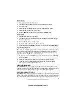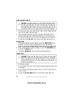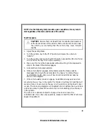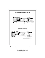
Brake Lights (Mandatory)
I
CAUTION: As a safety feature, the unit monitors the brake light to
prevent an unauthorized driver from driving the car and to switch to
normal engine operating condition. For this reason, the YELLOW
brake light input wire must be connected and the brake light must be
in working condition or the remote start will not operate properly.
1. Turn the ignition key to the "ON" position, then press the brake pedal and
make sure the brake light illuminates.
2. Use a voltmeter to find the one wire at the brake light switch (usually
located on the upper brake pedal arm) that shows +12 volts when you
press the brake pedal and 0 volts when the brake pedal is not depressed.
3. Connect the 18 ga YELLOW wire to the vehicle brake light switch wire.
Parking Lights
1. If the parking lights are positive trigger, connect the RED/WHITE wire to
the battery positive (+) terminal through the 20 amp fuse assembly.
NOTE: Do not connect the RED/WHITE wire to the control unit RED wire.
2. If the parking lights are negative (-) trigger, connect the RED/WHITE wire
to control unit BLACK wire.
3. Connect the RED/BLACK wire to the vehicle parking light wire.
Reverse Light
I
CAUTION: Some vehicles allow you to remove the gear shift
selector from "Park" even while the ignition key is not on. As a safety
feature, the system will monitor the reverse wire. If the vehicle is
removed from "Park" while in the remote start mode, the system will
shut down immediately.
1. Set the parking brake.
2. Turn the ignition key to the "ON" position and adjust the gear shift selector
to "Reverse."
3. Use a voltmeter to find the wire that will show +12 volts in "Reverse" and
0 volts in "Park."
4. Connect the YELLOW/BLACK wire to the vehicle’s reverse light wire.
10
PrimeStart 650 Installation Manual
Содержание PrimeStart 650
Страница 1: ...PrimeStart 650 Installation Manual...
Страница 2: ...PrimeStart 650 Installation Manual...
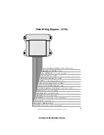
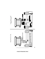
Страница 5: ...3 PrimeStart 650 Installation Manual Main Wiring Diagram 16 Pin...
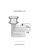
Страница 6: ...Main Wiring Diagram 12 Pin 4 PrimeStart 650 Installation Manual...
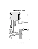
Страница 7: ...5 PrimeStart 650 Installation Manual Satellite Relay Module Diagram...
Страница 20: ...18 PrimeStart 650 Installation Manual...
Страница 21: ...19 PrimeStart 650 Installation Manual...
Страница 22: ...20 PrimeStart 650 Installation Manual...


