www.prideservice.com
www.quantumrehab.com
INFINFB1922/Rev. A/11-20-05
1 of 2
T
ECHNICAL
I
NSTRUCTIONS
GO-GO ELITE TRAVELLER MOTOR REPLACEMENT
DRVMOTR1269 — Motor with Power Connectors
If you require any assistance with these instructions, please call
Pride Technical Service
at
1-877-800-1248
.
Canada
providers
, phone
1-888-570-1113
.
NOTE: Any nylon insert lock nut removed during the disassembly or adjustment of the power chair, must be
replaced with a new nut. Nylon insert lock nuts should not be reused as it may cause damage to the nylon
insert, resulting in a less secure fit. Replacement nylon insert lock nuts are available at local hardware stores
or through your authorized Pride Provider.
Tools needed:
•
Standard and metric socket sets
•
Standard and metric hex key sets
•
Phillips screwdriver
Installation instructions:
1. Remove the key from the key switch. Refer to the owner’s manual.
2. Place the Elite Traveller into drive mode. Refer to the owner’s manual.
3. Separate the rear section of the scooter from the front section. Refer to the owner’s manual.
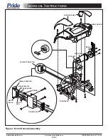
4. Remove the shroud panels from the rear shroud and remove the rear shroud. See figure 1.
5. Remove the hardware that fastens the power connector to the frame and remove the power connector. See figure 1.
6. Remove the hardware that fastens the motor assembly to the transaxle and remove the motor assembly from the
transaxle. See figure 1.
7. Clip any wire ties that fasten the motor harness to the frame or the brake harness.
8. Remove the female housing from the power connector. See figure 1.
NOTE: Make sure that you keep the spring. The connector will not operate correctly without it.
9. Remove the female housing cap from the female housing. See figure 1.
10. Remove the two motor leads (red and black) from the female housing. See figure 1.
11. Remove the hardware that fastens the brake to the motor and remove the brake.
12. Install the brake onto the new motor (A1). Make sure that the new brake handle is pointing up (freewheel position) so
that the screw holes line up properly with the motor.
13. Install the motor and brake leads into the power connector. The leads must be installed in the exact positions as noted
in figure 1.
14. Reassemble the female housing and the female housing cap.
15. Reassemble the female housing into the power connector.
16. Install the new motor assembly. Use the new hardware supplied with the kit. Make sure that the coupler is facing the
correct direction. See figure 1.
17. Reinstall the power connector onto the frame. Do not tighten the screws.
18. Replace the wire ties used to fasten the motor harness to the frame or the brake harness.
19. Connect the front and rear sections of the scooter.
20. Tighten the screws on the power connector.
21. Reinstall the rear shroud and the shroud panels.
22. Reassemble the scooter. The Go-Go Elite Traveller is now ready for use.
Kit Contents:
REF# QTY PART NUMBER
DESCRIPTION
A1
1
DRVMOTR1269 MOTOR,CCL,W/POWER CONNECTOR,SC40E/44E,(CM808-031A)


