Section 16: SUPPLEMENT INFORMATION ON INDEPENDENT FRONT SUSPENSION (IFS)
16-28
2. Torque bushing collar nuts to 70 - 80 lbf•ft
(95 - 110 N•m).
3. Torque sway bar link upper nuts to 215 - 225
lbf•ft (290 - 305 N•m) and lower nuts to 70 - 80
lbf•ft (95 - 110 N•m).
7.2 Sway Bar (Drive Axle)
7.2.1 Removal
1. Disconnect the two links from sway bar.
2. Safely support the sway bar. Unbolt the four
bushing collars from subframe.
3. Remove sway bar.
Note:
Sway bar bushings are slitted to ease their
removal.
7.2.2 Installation
1. Loosely install the sway bar.
2. Torque the eight bushing collar nuts to 70 - 80
lbf•ft (95 - 110 N•m).
3. Torque sway bar link upper nuts to 215 - 230
lbf•ft (290 - 305 N•m) and lower nuts to 70 - 80
lbf•ft (95 - 110 N•m).
8. INDEPENDENT FRONT
SUSPENSION ADJUSTMENT
Converted coach shell is equipped with "LEVEL-
LOW" leveling system. The purpose of the
"LEVEL-LOW" is to adjust suspension in three
separate points (front, rear right and rear left air
springs) in order to level vehicle body. Three
height control valves, automatically control air
pressure in the three separate points (air springs)
and maintains a constant vehicle height regard-
less of load, or load distribution. The control sole-
noid valve supplies air to the five way three-
position air control valve, which bypasses the
height control valve, and opens a passage to
allow the air control and exhaust valve to re-
lease/supply air from airs springs. To improve
road comfort, an expansion air tank is installed in
series with each air springs.
In addition to the above suspension components
the system also includes : sway bar, upper and
lower suspensions, bars and shock absorbers
(Fig. 1).
Note:
Only for preliminary adjustment, refer to
figure 15. Torque rod length must be fixed to 23
9/64" (588 mm) and relay rod to 22 13/32"
(569 mm).
Caution :
Parts must be replaced by ones with
the same part numbers or with equivalent parts,
if replacement becomes necessary. Do not use
parts of lesser quality or substitute design.
Torque values must be used as specified during
reassembly to assure proper retention of these
parts.
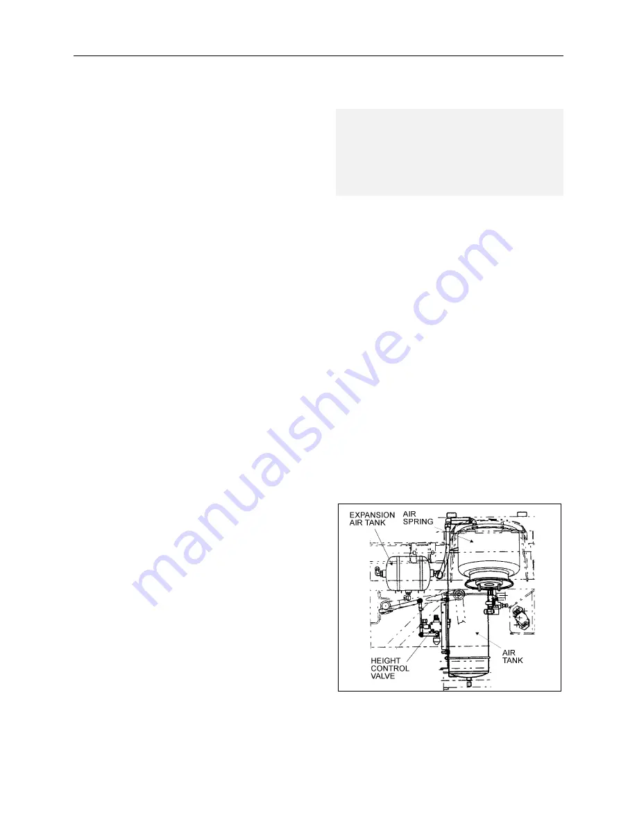
8.1 Suspension Height
Adjustment
The flow of pressurized air from the accessory air
tank to the air springs is controlled by three height
control valves. The two rear valves are mounted
to the subframe and connected to the rear axles
through an arm and link connection. The front
valve is mounted to the subframe and connected
to the front air tank support (Fig. 22). These con-
nections allow the valves to apportion air pressure
in the springs to the vehicle load, maintaining
normal ride height.
Immediate response height control valves in-
crease or decrease the air pressure in the sus-
pension system as required. One height control
valve is located at center of front sway bar, and
regulates air to front suspension air springs in
order to maintain the vehicle at the required
height. Two are located at the drive axle, one on
each inner side of rear wheelhousing.
FIGURE 22: HEIGHT CONTROL VALVE LOCATION
16057
Содержание GKN AXLES LIMITED KIRKSTALL DIVISION
Страница 24: ...Section 16 SUPPLEMENT INFORMATION ON INDEPENDENT FRONT SUSPENSION IFS 16 7 FIGURE 6 CLAMPS POSITIONING 16041...
Страница 32: ...Section 16 SUPPLEMENT INFORMATION ON INDEPENDENT FRONT SUSPENSION IFS 16 15 FIGURE 12 BALL JOINT 16047...
Страница 36: ...Section 16 SUPPLEMENT INFORMATION ON INDEPENDENT FRONT SUSPENSION IFS 16 19 FIGURE 14 BALL JOINT 16049...
Страница 66: ...12 FIGURE 8 HUB UNIT AND STUB AXLE 10023...


