84
Prestigio Cavaliere 141
Technical Service Manual
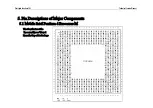
5. Pin Descriptions of Major Components
Host Bus Inter face
Name
Pin Attr
Signal Descr iption
FERR#
I
1.1V/2.65V -M
Floating Point Er r or :
CPU will assert this signal upon a floating point error occurring.
IGNNE#
OD
1.1V/2.65V -M
Ignor e Numer ic Er r or :
IGNNE# is asserted to inform CPU to ignore a numeric error.
NMI
OD
1.1V/2.65V -M
Non-Maskable Inter r upt:
A rising edge on NMI will trigger a non-maskable interrupt to
CPU.
INTR
OD
1.1V/2.65V -M
Inter r upt Request:
High-level voltage of this signal conveys to CPU that there is
outstanding interrupt(s) needed to be serviced.
APICD[1:0]
I/OD
1.1V/2.65V -M
APIC Data:
These two signals are used to send and receive APIC data.
CPUSLP#/
CPUSTP#
OD
1.1V/2.65V -M
CPU Sleep:
The CPUSLP# can be used to force CPU enter the Sleep state.
CPU Clock STOP:
For Intel Mobile processor, this signal can be used to stop the
clock to the processor. If the processor is in Quick Start state
and the processor clock is stopped, the processor will enter the
Deep Sleep state.
For AMD processor, this signal can be to reduce processor
voltage during C3/S1 state.
STPCLK#
OD
1.1V/2.65V -M
Stop Clock:
STPCLK# will be asserted to inhibit or throttle CPU activities
upon a pre-defined power management event occurs
INIT#
OD
1.1V/2.65V -M
Initialization:
INIT is used to re-start the CPU without flushing its internal
caches and registers. In Pentium III platform it is active high.
This signal requires an external pull-up resistor tied to 3.3V.
APICCK
I
2.5V - M
APIC Clock:
This signal is used to determine when valid data is being sent
over the APCI bus.
A20M#
OD
1.1V/2.65V- M
Address 20 Mask:
When A20M# is asserted, the CPU A20 signal will be
forced to “0”
MuTIOL Connect Inter face
Name
Pin Attr
Signal Descr iption
ZCLK
I
3.3V - M
Megaband I/O Connect Clock
ZUREQ
I/O
1.8V - M
Megaband I/O Conect Controll pins
ZDREQ
I/O
1.8V - M
Megaband I/O Conect Controll pins
ZSTB[1:0]
I/O
1.8V - M
Megaband I/O Connect Strobe
ZSTB[1:0]#
I/O
1.8V - M
Strobe Compliment
ZAD[15:0]
I/O
1.8V - M
Address/Data pins
ZVRE
I -M
Megaband I/O Connect I/O reference voltage
ZCMP_N
I -M
N-MOS Compensation Input
ZCMP_P
I -M
P-MOS Compensation input
Gener al Pur pose I/O
Signal Name
Pin Attr
Signal Descr iption
GPIO[6:0]
I/O
3.3V/5V -M
GPIO:
Can be a general purpose input or output.
GPIO14,[12:7]
I/O
3.3V/5V -AUX
GPIO :
Can be a general purpose input or output.
GPIO13
O
3.3V/5V - AUX
GPO:
Can be a general purpose output.
GPIO[18:15]
O
3.3V/5V - AUX
GPO:
Can be a general purpose output.
GPIO[20:19]
I/O
3.3V/5V - AUX
GPIO:
Can be a general purpose input or output.
5.3 SiS961(MuTIOL® Media I/O South Bridge )
Содержание CAVALIERE 141
Страница 1: ...PRESTIGIO CAVALIERE 141 TECHNICAL SERVICE MANUAL...
Страница 141: ...w w w p r e s t i g i o c o m...


