background image

99

Prestigio Cavaliere 141

Technical Service Manual

Where

From Power Source

Problem(First use

AC to power it)

Check following parts and signals:

PARTS:                               SIGNAL:               

Board-level

Troubleshooting

Replace

Motherboard

No power

Connect 

AC adaptor

or battery

Replace the faulty

AC adaptor ,

charge BD or 
Battery.

Power

OK?

No

Yes

No

No

Try another known good battery,charge BD 

or AC adapter.

Yes

Yes

AC

Battery

Is the

Notebook connected

to power (Either AC adaptor

or battery)?

Check following parts and signals:

PARTS:                              SIGNAL:               

ADINP
D/VMAIN
VDD5S
D/ADEN#
D/LEARNING
PWR_VDDIN
H8_AVREF
SW_VDD5
SW_VDD5#

D/VMAIN
D/BATT_V
D/BATT_T
D/BATT_DEAD

M/B

Charge BD

PJ501
PL3
PL4
PD5
PD6
PF2
PU10

PQ7~9
PQ13~16
PR30
PR23
PR44
PR45

U13
U15
Q26
D501
R670
F5
D8
Q21~23

M/B

Charge BD

PF1       
PC2     
PL1      
PL2      
PR5      
PR4    
PC1
PU10

U13
Q26
D501
R670

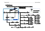
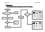
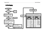
When the power button is pressed, nothing happens ,power indicator does not light up.

PR47
PR48
PR41
PR38
PQ12
PC52
PC50
PC60

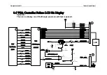
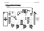
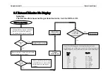
8.1 No Power:

Содержание CAVALIERE 141

Страница 1: ...PRESTIGIO CAVALIERE 141 TECHNICAL SERVICE MANUAL...

Страница 2: ...Spec 2 System View and Disassembly 2 1 System View 2 2 System Disassembly 3 Definition Location of Connectors Switches 3 1 Mother Board A 3 2 Mother Board B 3 3 Charge Board 4 Definition Location of...

Страница 3: ...lure LCD No Display 8 5 External Monitor No Display 8 6 Memory Test Error 8 7 Keyboard K B and Touch Pad T P Test Error 8 8 Hard Drive Test Error 8 9 CD ROM Drive Test Error 8 10 USB Port Test Error 8...

Страница 4: ...ng F2 key at system start up or warm reset System also provides icon LEDs to display system status such as AC Power indicator CD ROM HDD NUM LOCK CAP LOCK SCROLL LOCK SUSPEND MODE and battery present...

Страница 5: ...oder with Macrovision Ver 7 1 L1 option for TV display 2 A LVDS transmitter with bi linear scaling capability for TFT LCD panel display SiS301LV receives digital video signals and control signals from...

Страница 6: ...2001 North Bridge SiS650 South Bridge SiS961 TV OUT and display controller SiS301LV LPC to ISA and super I O controller NS PC87393 Keyboard System Hitachi H8 3437 Universal Controller FAX MODEM Askey...

Страница 7: ...of performance in multimedia applications including 3 D graphics video decoding encoding and speech recognition Use Source Synchronous Transfer SST of address and data to improve performance by transf...

Страница 8: ...ility and Fast Write Transactions A high bandwidth and mature SiS MuTIOL technology is incorporated to connect SiS650 and SiS961 MuTIOL Media I O together SiS MuTIOL technology is developed into three...

Страница 9: ...mory Controller in the width of 128 bits are devised to ensure concurrency of Host t GUI streaming and GUI t MC streaming In PC133 or DDR266 memory subsystem the 128 bits GUI t MC bus will attain the...

Страница 10: ...TSEG SMRAM Support Defer function to maximize bus utilization Support Dynamic Bus Inversion AGTL AGTL compliant bus driver auto compensation 64 Bit High Performance DDR266 PC133 Memory Controller Supp...

Страница 11: ...ndow Size from 4MBytes to 256MBytes Supports Pipelined Process in CPU to A G P Access Supports 8 Way 16 Entries Page Table Cache for GART to Enhance A G P Controller Read Write Performance Supports PC...

Страница 12: ...gh Quality 3D Accelerator Built in a high performance 256 bit 3D engine Built in a high quality 3D engine High Performance 2D Accelerator Built in 128 double words hardware command queue Built in Dire...

Страница 13: ...irect DVD to TV playback Video Accelerator Supports single frame buffer architecture Supports single video windows with overlay function Supports YUV to RGB color space conversion Supports bi linear v...

Страница 14: ...in 64x128 CRT FIFOs to support ultra high resolution graphics modes and reduce CPU wait state Built in programmable 24 bit true color RAMDAC up to 333 MHz pixel clock Built in two clock generators Bu...

Страница 15: ...ration registers for supporting ACPI power down controller Power down all internal macro cells such as SRAM DAC clock generator when power saving mode Supports clock stopping for video accelerator VP...

Страница 16: ...separate modem codec The integrated Fast Ethernet MAC Controller features an IEEE 802 3 and IEEE 802 3x compliant MAC with external LAN physical layer chip supporting full duplex 10 Base T 100 Base T...

Страница 17: ...OL technology is developed into three layers the Multi threaded I O Channels Layer delivering 1 2GB bandwidth to connect embedded DMA Master devices and external PCI masters to interface to Multi thre...

Страница 18: ...nt Execution among Multi I O Devices Integrated MuTIOL to PCI Bridge PCI 2 2 Specification Compliance Supports up to 6 PCI Masters Two Prefetch cache Buffers support 2 delayed transactions Fairness Ro...

Страница 19: ...ompatible Supports Enhanced Software and Automatic Polling schemes to access PHY registers Supports full duplex 10base T 100base Tx 1 Mb s 10 Mb s Home Networking Support ACPI v1 0b and PCI Power Mana...

Страница 20: ...ACPI Sleep States Include S1 S3 S4 S5 CPU Power States Include C0 C1 C2 C3 C4 Supports Intel Deeper Sleep Power State for Intel mobile processor Reduce AMD processor voltage during S1 C3 state Power...

Страница 21: ...a Transfer Distributed DMA Support Integrated Interrupt Controller Two 8259A Compatible Interrupt Controllers for up to 15 interrupts Programmable Level or Edge Triggered Interrupts Support Serial Int...

Страница 22: ...rd Power Up System Sleep and Power Up by Hot Key KBC and PS2 Mouse Can Be Individually Disabled Integrated Multimedia Timers Support three timers operating at 32 or 64 bit mode Integrated PCI to LPC B...

Страница 23: ...ation can be one of the three 1 Primary CRT SiS301LV TV 2 Primary CRT SiS301LV LCD 3 SiS301LV TV SiS301LV LCD 1 2 6 Super I O_NS PC87393 National Semiconductor s PC8739x family of LPC Super I O device...

Страница 24: ...ith 48 kbyte ROM and 2 kbyte RAM and the H8 3434 with 32 kbyte ROM and 1 kbyte RAM The H8 3437 H8 3436 and H8 3434 are available in mask ROM versions The H8 3437 and H8 3434 are also available in ZTAT...

Страница 25: ...is MNP Class 5 Error Correction V 42 LAPM and MNP2 4 FAX mode capabilities ITU T V 17 V 29 V 27ter and V 21 CH 2 TIA EIA 578 Class 1 FAX V 80 Host Controlled Communication Protocol Standards H 324 Int...

Страница 26: ...or exchanging command and status information with a Station Management STA entity The ICS1893 Media Dependent Interface MDI can be configured to provide either half or full duplex operation at data ra...

Страница 27: ...to parallel single slot PC Card power interface switches Up to five general purpose I Os Programming output select for CLKRUN Five PCI memory windows and two I O windows available to the 16 bit PC Car...

Страница 28: ...n Compatible with 3 3V 5V and 12V PC Cards Break before make switching 1 2 11 AC 97 Codec _ Realtek ALC201 20 bit Stereo Digital to Analog Converter and 18 bit Stereo Analog to Digital Converter with...

Страница 29: ...rammable Over Under Temperature Limits Programmable Conversion Rate 2 Wire SMBus Serial Interface Supports System Management Bus SMBus Alert 200 _A Max Operating Current 1 _A Standby Current 3 V to 5...

Страница 30: ...CRT switching Rotate display mode in LCD only CRT only and simultaneously display Fn F6 Brightness down Decreases the LCD brightness Fn F7 Brightness up Increases the LCD brightness Fn F8 Brightness M...

Страница 31: ...enable hibernate function in power management to power button function Continue pushing power button over 4 seconds will force system off at ACPI mode 1 3 3 Cover Switch System automatically provides...

Страница 32: ...BATTERY POWER This LED lights green when the notebook is being powered by Battery and flash on 1 second off 1 second when Suspend to DRAM is active using Battery power The LED is off when the noteboo...

Страница 33: ...m beeps per 2 seconds System will Suspend to HDD after 2 Minutes to protect users data 1 3 5 2 Battery Low State After Battery Warning State and battery capacity is below 4 system will generate beep f...

Страница 34: ...life at less 220mAh 5 8uA 4 years Battery was put in battery holder can be replaced 1 3 8 I O Port One Power Supply Jack One External CRT Connector For CRT Display One S Video TV Output Connector Sup...

Страница 35: ...eral Components 1 4 1 LCD PANEL 1st Source QDI 14 1 TFT QD141X1LH03 MP01 2nd Source Chi Mei 14 1 TFT N141X6 L0 Please reference the spec for detail 1 4 2 Ext Floppy Disk Drive External USB 3 5 1 44MB...

Страница 36: ...QSI SDR 083 1 4 5 COMBO Drive 1st source KME UJDA730 MT A 2nd source QSI SBW 161 16X Combo 3rd source NEC CB2100A 1 4 6 Keyboard JME 19mm pitch 3 0mm stroke 1 4 7 Track Pad Synaptics TM41PUM311 2 Accu...

Страница 37: ...face SEE ESD Testing specification PN 520 000270 01 Power supply voltage 5 0Voltage 10 Power supply current 4 0mA max operating 1 4 8 Fan HY45J05 001 1 5 Power management The Prestigio Cavaliere 141 s...

Страница 38: ...save battery power without loosing much computing capability The CPU power consumption and temperature is lower in this mode 1 5 1 3 Standby mode For more power saving it turns of the peripheral comp...

Страница 39: ...powered on again 1 5 2 Other power management functions 1 5 2 1 HDD Video access System has the ability to monitor video and hard disk activity User can enable monitoring function for video and or har...

Страница 40: ...SPDIF GPIO MAIN GPIO1 LDRQ1 GPIO MAIN GPIO2 THERM GPIO MAIN GPIO3 EXTSMI GPIO MAIN GPIO4 CLKRUN GPIO MAIN GPIO5 PREQ5 GPIO MAIN GPIO6 PGNT5 GPIO MAIN GPIO7 GPWAK GPIO AUX GPIO8 RING GPIO AUX GPIO9 AC...

Страница 41: ...UX GPIO17 PMDAT VGATEM GPO AUX GPIO18 PMCLK RTC32KH Z GPO AUX GPIO19 Reserved for CLK GPIO AUX GPIO20 Reserved for Data GPIO AUX GPIO21 EESK GPI AUX GPIO22 EEDI GPI AUX GPIO23 DDEO GPI AUX GPIO24 EECS...

Страница 42: ...ic NorthBridge SiS650 SouthBridge SiS961 L2Cache 512KB ondie SystemBIOS Insyde256KB FlashEPROM IncludesSystemBIOS VGA BIOS andPlug Play capability ACPI Memory 128MB DDRSDRAM onboardwithoneexpansionDDR...

Страница 43: ...S and Europe PointingDevice Glidepadwith2buttonsandscroll button 4directional scroll PCMCIA 1TypeII slot CardBusport support Audio Twospeaker 1Woutput Build inmicrophone Build inAC Link Audiocontrolle...

Страница 44: ...Li ON 4S2P Battery ACadapter Input 100 240V 50 60HzAC CPO Dimensions 310x277x29mm front side 33mm back side Weight 3 0Kg Software Windows2000 ME XP XPPro Indicater 3LEDsfor Power Battery status onInve...

Страница 45: ...bly Disassembly 2 1 System View 2 1 1 Front View n Microphone Connector o Audio Input Connector p Audio Output Connector q Top Cover Latch 2 1 2 Left Side View n VGA Port o S Video Output Connector p...

Страница 46: ...cal Service Manual 2 1 3 Right Side View n CD ROM DVD ROM Drive o USB Ports p Power Connector 2 1 4 Rear View n Battery Charge Indicator o Battery Power Indicator p AC Power Indicator q Battery Pack o...

Страница 47: ...DIMM cover o CPU cover p Hard Disk Drive cover q Battery Pack o q n p 2 1 6 Top Open View n LCD Screen o Stereo Speaker p Keyboard q Touch Pad r Device LED Indicators s Power Button t Battery Charge I...

Страница 48: ...ponents from the notebook NOTE Before you start to install replace these modules disconnect all peripheral devices and make sure the notebook is not turned on or connected to AC power Modular Componen...

Страница 49: ...pack out of the compartment o while sliding and holding the release lever outwards to the unlock position n Figure 2 1 Figure 2 1 Remove the battery pack Reassembly 1 Push the battery pack into the c...

Страница 50: ...y pack See section 2 2 1 disassembly 2 Remove one screw fastening the LED cover on the bottom of the notebook Figure 2 2 Figure 2 2 Remove one screw Figure 2 3 Remove the LED panel 3 Open the top cove...

Страница 51: ...en disconnect the cable from system board to detach the keyboard Figure 2 4 Figure 2 4 Disconnect the cable Reassembly 1 Reconnect the keyboard cable and fit the keyboard back into place 2 Fit the LED...

Страница 52: ...e battery pack See section 2 2 1 disassembly 2 Remove two screws fastening the CPU compartment cover Figure 2 5 Figure 2 5 Remove the CPU compartment cover Figure 2 6 Remove the heat sink 3 Remove fou...

Страница 53: ...rowhead corner of the CPU with the beveled corner of the socket and insert the CPU pins into the holes Place the lever back to the horizontal position and push the lever to the left 2 Reconnect the fa...

Страница 54: ...notebook upside down And remove the battery pack See section 2 2 1 disassembly 2 Remove two screws fastening the HDD compartment cover and lift the cover up Figure 2 8 Figure 2 8 Remove the HDD cover...

Страница 55: ...e 2 10 Figure 2 10 Free the HDD drive Reassembly 1 To install the hard disk drive place it in the bracket and secure with four screws 2 Put the hard disk drive in the compartment and slide it inwards...

Страница 56: ...D DVD ROM 3 Put the notebook back to the upright position Then insert a small rod such as a straightened paper clip into the drive s manual eject hole and push firmly to release the tray Pull the tray...

Страница 57: ...2 13 Remove the cover Figure 2 14 Remove the SO DIMM 3 Pull the retaining clips outwards n and remove the SO DIMM o Figure 2 14 Reassembly 1 To install the SO DIMM match the SO DIMM s notched part wit...

Страница 58: ...s See Figure 2 15 Figure 2 15 Remove two hinge covers Figure 2 16 Separate the LCD assembly 2 Disconnect the two LCD cables from the system board and remove four screws of the hinges Now you can separ...

Страница 59: ...2 2 7 Disassembly 3 Remove the four rubber pads and four screws on the corners of the panel Figure 2 17 Figure 2 17 Remove LCD frame Figure 2 18 Remove LCD panel 4 Insert a flat screwdriver to the low...

Страница 60: ...ket Reassembly 1 Attach the LCD bracket on the LCD panel and secure with four screws 2 Fit the LCD panel back into place and secure with four screws and reconnect the cable to the inverter board 3 Fit...

Страница 61: ...tions 2 To remove the inverter board on the bottom of the LCD assembly disconnect the cable and remove two screw Figure 2 20 Figure 2 20 Remove the inverter board Reassembly 1 Fit the inverter board b...

Страница 62: ...CD DVD ROM drive and LCD assembly See the Disassembly parts in previous sections 2 Remove the keyboard See section 2 2 2 disassembly and disconnect the touch pad cable from system board Figure 2 21 Fi...

Страница 63: ...ompartment of the notebook Then remove the bottom housing Figure 2 23 Figure 2 23 Remove seven screws Figure 2 24 Loose the system board 6 Remove one screw fastening the charge board and disconnect th...

Страница 64: ...d two nuts fastening the system board on the cover assembly Then disconnect the left speaker cable from the system board Figure 2 25 Figure 2 25 Remove the system board Figure 2 26 detach the LED boar...

Страница 65: ...ure with six screws and two nuts Then reconnect the left speaker cable 3 Replace the charge board and secure with one screw Then reconnect the right speaker cable 4 Fit the bottom housing and secure w...

Страница 66: ...Figure 2 27 Figure 2 27 Remove the touch pad holder Figure 2 28 Remove the touch pad shield 3 To tack the touch pad out remove the ten screws fastening the touch pad shield Figure 2 28 Reassembly 1 R...

Страница 67: ...rts in previous sections 2 Disassembly the notebook to access the system board See section 2 2 10disassembly 3 Remove the two screws fastening the modem card and then disconnect the cable from system...

Страница 68: ...er Board A J504 J506 J508 J510 J502 J515 J514 J513 J509 J512 J509 J511 J505 J502 LED Board Connector J504 VGA Connector J505 Primary IDE Connector J506 TV Out Connector J508 LAN Connector RJ45 J509 DD...

Страница 69: ...3 2 Mother Board B J1 LCD Connector J2 LCD Inverter Board Connector J3 Charge Board Connector J4 Internal KB Connector J5 Touch Pad Connector J7 Transform Board Connector MDC SW2 SW_LEFT SW3 SCRL_UP S...

Страница 70: ...rvice Manual 3 Definition Location of Connectors Switches 3 3 Charge Board Side A J1 J1 Charge Board to MB Connector J501 Battery Connector J503 J504 USB Connector PJ50 Power Jack Side B Right Side Vi...

Страница 71: ...11 J509 U509 U510 U512 U513 U514 U506 U505 U503 SiS301LV LVDS Interface U505 SiS650 North Bridge U506 P4 478 CPU Socket Mobile P4 U507 ES824 DATA Buffer U508 ICS952001 Clock Generator U509 ICS1893 LAN...

Страница 72: ...71 Prestigio Cavaliere 141 Technical Service Manual 4 Definition Location of Major Components 4 2 Mother Board B U11 CP2211 Card Bus Power Controller U13 F3437 H8 U19 PC87393 Super I O U13 U19 U11...

Страница 73: ...72 Prestigio Cavaliere 141 Technical Service Manual 4 Definition Location of Major Components 4 3 Charge Board Side A PU9 PU9 TL594C Pulse Width Modulation Controller...

Страница 74: ...Prestigio Cavaliere 141 Technical Service Manual 5 Pin Descriptions of Major Components 5 1 Mobile Intel Pentium 4 Processor M The Coordinates of the Processor Pins as Viewed From the Top of the Packa...

Страница 75: ...AP1 AP0 Pin Name Type No Description BCLK 1 0 Input The differential pair BCLK Bus Clock determines the system bus frequency All processor system bus agents must receive these signals to drive their...

Страница 76: ...3 3 Furthermore the DBI pins determine the polarity of the data signals Each group of 16 data signals corresponds to one DBI signal When the DBI signal is active the corresponding data group is invert...

Страница 77: ...Intel 845MP 845MZ Chipset Platform Design Guide Pin Name Type No Description GTLREF Input GTLREF determines the signal reference level for AGTL input pins GTLREF should be set at 2 3 VCC GTLREF is use...

Страница 78: ...have on die termination and must be terminated on the system board Pin Name Type No Description ITPCLKOUT 1 0 Output ITPCLKOUT 1 0 is an uncompensated differential clock output that is a delayed copy...

Страница 79: ...ges Vcc Unlike some previous generations of processors these are open drain signals that are driven by the Mobile Intel Pentium 4 Processor M and must be pulled up to 3 3V max with 1Kohm resistors The...

Страница 80: ...HD 47 32 DBI2 are latched by HDSTBN2 HD 63 48 DBI3 are latched by HDSTBN3 HNCOMP I M GTL N MOS Compensation Input Host BUS Inter face Continue Name Pin Attr Signal Descr iption CPUCLK CPUCLK I 0 71V M...

Страница 81: ...ta Bus CKE 5 0 O open drain 2 5V 3 3V AUX SDRAM Clock Enable S3AUXSW CKE6 O open drain 2 5V 3 3V AUX Aux power switch for ACP I S3 state low active DDRVREF A B I M DDR I O Reference Voltage Power and...

Страница 82: ...AO Analog M Green Signal Output BOUT AO Analog M Blue Signal Output SiS M uTIOL Inter face Signal Name Pin Attr Signal Descr iption ZCLK I 3 3V M SiS MuTIOL Connect ZUREQ ZQREQ I O 1 8 M SiS MuTIOL Co...

Страница 83: ...O 3 3V 5V M Hardware Trap pin refer to section 5 DRAM_SEL I 3 3V 5V AUX Hardware Trap pin refer to section 5 TRAP 1 0 I 3 3V 5V M Hardware Trap pins refer to section 5 ENTEST I 3 3V 5V M Test Mode en...

Страница 84: ...1 8V 3 3V M Channel B Data VBD 11 0 multiplexed with AAD VAHSYNC I O 1 8V 3 3V M Channel A H Sync VAHSYNC multiplexed with AAD18 VAVSYNC I O 1 8V 3 3V M Channel A V Sync VAVSYNC multiplexed with AAD17...

Страница 85: ...ttle CPU activities upon a pre defined power management event occurs INIT OD 1 1V 2 65V M Initialization INIT is used to re start the CPU without flushing its internal caches and registers In Pentium...

Страница 86: ...that the target has driven valid data onto the PCI bus For a write cycle TRDY indicates that the target is prepared to accept data from the PCI bus When the SiS961 is a PCI master it is an input pin S...

Страница 87: ...cause the PSON to go low and hence turn on the power supply When the system is in suspend mode an active PME event will cause the system wakeup and generate an SCI SMI PSON OD 5V AUX ATX Power ON OFF...

Страница 88: ...tem is in stable operating state During the period of PWROK being low PCIRST will all be asserted until after PWROK goes high for 12 ms AC 97 Interface Name Pin Attr Signal Description AC_BIT_CLK I 3...

Страница 89: ...sical unit RXD 0 3 I 3 3V 5V AUX Receive Data This is a group of 4 data signals aligned on nibble boundaries which are driven synchronous to the RXCLK by the external physical unit MAC Interface Conti...

Страница 90: ...Tolerance Power Plane Type Attribute VSS 0V GROUND Digital VSSZ 0V GROUND Digital IVDD 1 8V MAIN Digital PVDDZ 1 8V MAIN Digital VDDZ 1 8V MAIN Digital VDDZCMP 1 8V MAIN Analog VSSZCMP 0V GROUND Anal...

Страница 91: ...ANPHY MII U522 AC97 CODEC MIC Line Out AC Link U521 Amplifier U13 H8 CRT U515 PCI1410 J511 PC Card Socket USB LPC Bus Hyper ZIP Bus U19 Super I O PC87393 LCD LCD U503 LVDS Interface VB Bus J7 MDC TV J...

Страница 92: ...our computer If an error is detected during these tests you will see an error message displayed on the screen If the error occurs before the display is initialized then the screen cannot display the e...

Страница 93: ...aliere 141 MB have reserved eight LEDs that are parallel connection with PIO output lines Figure 1 when the system BIOS write the error code to Port 378 the LEDs can show the messages Maybe the LEDs h...

Страница 94: ...te 37H Protected mode exit successful 38H Update OUTPUT port 39H Setup Cache Controller 3AH Test If 18 2Hz Periodic Working 3BH Test for RTC ticking 3CH Initialize the hardware vectors 3DH Search and...

Страница 95: ...Code Description 3EH Update NUMLOCK status 3FH Special init of COMM and LPT ports 40H Configure the COMM and LPT ports 41H Initialize the floppies 42H Initialize the hard disk 43H Initialize option R...

Страница 96: ...attery Can not Be Charged 8 9 CD ROM Driver Test Error 8 3 No Display 8 10 USB Port Test Error 8 11 PC Card Socket Test Error 8 4 LCD No Display or Picture Abnormal 8 12 LAN Test Error 8 5 External Mo...

Страница 97: ...Charge Discharge PQ13 PQ16 PD16 J1 J3 8677 DD BOARD PL1 PL2 PU501 PU1 PU10 CPU_CORE P31 PU502 PU13 PU14 2 5V_P P30 JO8 JO9 2 5V_DDR P32 Discharge SVDDZCMP L526 VCLK_DDR P9 L525 VCLK_DDRA R94 R97 P9 DD...

Страница 98: ...11 ECLKAVDD P7 L508 TVPLL_VCC P10 L509 TVPLL_VCC P10 L5 VDDT P10 L510 P10 L506 LVDD4 5 P10 L503 LVDD2 P10 L505 LVDD0 1 P10 L507 LPLL_VDD P10 Q1 3V_LCDVCC P14 L535 L534 SZ1XAVDD P15 SZ4XAVDD P15 Page 3...

Страница 99: ...1 25V PR38 3 3k 5 6 7 PR48 100k D VMAIN PQ12 SCK431 8 PF1 TR SFT 10A PC2 0 1U PL1 PL2 PR5 301k PR4 100k 30 38 D501 R670 2 2k 1 PR44 4 7k 1 3 PR19 0 01 S D 2 3 1 6 7 8 5 G 4 PR23 470k PR30 100k PQ7 2N...

Страница 100: ...adapter Yes Yes AC Battery Is the Notebook connected to power Either AC adaptor or battery Check following parts and signals PARTS SIGNAL ADINP D VMAIN VDD5S D ADEN D LEARNING PWR_VDDIN H8_AVREF SW_VD...

Страница 101: ...G PU2A SI4925DY PU2B SI4925DY PU10A PD3 RLZ20C PR17 4 7K PR10 100K PD8 BAS32L PD4 EC31QS04 12 PQ2 SI4835DY PR18 10K PC19 1000P 5 6 1 16 8 11 2 PQ3 PU8 TL594C RT CT 2IN VCC C1 C2 1IN 1IN PR16 4 7K PR36...

Страница 102: ...cted to power AC adaptor 1 Make sure that the battery is good 2 Make sure that the battery is installed properly Correct it Battery charge OK Check the following parts for cold solder or one of the fo...

Страница 103: ...0 0 100 0 133 3 80 0 66 7 33 3 1 1 0 0 1 100 0 134 5 67 2 66 7 33 3 0 0 0 1 1 100 0 133 3 66 7 66 7 33 3 0 0 1 1 1 100 0 133 3 100 0 66 7 33 3 1 0 1 1 0 133 3 133 3 66 7 66 7 33 3 1 0 1 1 1 133 3 166...

Страница 104: ...100M L525 120Z 100M 3 12 23 10 P9 VCLK_DDRA VCLK_DDR L528 120Z 100M L523 120Z 100M L22 120Z 100M L527 120Z 100M 3V 3V 3V 3V U508 3V L529 120Z 100M 13 19 P9 L521 120Z 100M L532 120Z 100M 3V 3V 3V L21 1...

Страница 105: ...2 1 3 8677 P4 D D Module R140 10K R141 1K 8677 2 5V 1 8V Module H8_PWRON PWRON SB_PWRBTN PWROK CPU_RST CPU_PWRGOOD PCIRST R92 0 U522 AC97 ALC202 AC97_RESET P19 P20 11 25 J7 MDC U505 North Bridge SiS65...

Страница 106: ...e to find out which part is causing the problem Yes No No Display One of the following parts on the mother board may be defective use an oscilloscope to check the following signal or replace the parts...

Страница 107: ...7 12 14 11 13 6 8 TXOUTCLK1 TXOUTCLK1 TXOUT11 TXOUT11 TXOUT12 TXOUT12 TXOUT10 TXOUT10 12V R3 470K 3V_LCDVCC Q1 NDS9410 R1 120Z 100M R2 10K 1 2 3V FPVCC 2 3 1 6 7 8 5 4 1 3 2 F1 3216FF 1A 3 2 1 PCIRST...

Страница 108: ...e BD J2 J1 are cold colder VGA Controller Failure Display OK Remove all the I O device cable from motherboard except LCD panel or extended monitor Display OK Yes No Yes No Re soldering One of the foll...

Страница 109: ...5 External Monitor No Display Symptom The CRT monitor shows nothing or abnormal color but it is OK for LCD VGA_RED VGA_HSYNC VGA_VSYNC VGA_DDCK VGA_DDDA 1 3 13 14 12 15 CON_VSYNC CON_DDCK CON_DDDA G...

Страница 110: ...tor Yes No Yes No Yes Re soldering No One of the following parts on the mother board may be defective use an oscilloscope to check the following signal or replace the parts one at a time and test afte...

Страница 111: ...CLK 3 4 CLK 3 4 U7 U8 U9 U10 J509 U511 U512 U513 U514 2 5V_DDR MD 0 63 U516 South Bridge SiS961 SODIMM Socket P6 P16 P9 P12 P11 DDR_MD 0 63 DDR_DQM 0 7 DDR_ DQS 0 7 RP11 RP12 0 8 RP4 0 4 DDR_CKE 2 3 D...

Страница 112: ...are OK 3 Then try another known good DIMM modules Memory Test Error One of the following components or signals on the motherboard may be defective Use an oscilloscope to check the signals or replace t...

Страница 113: ...R101 0 KBD_US JP J4 R174 4 7k 5V SW2 SW4 R575 0 J5 1 2 3 4 8 7 6 5 5V L19 600Z 100M H8_KBCS 8 93 96 97 53 54 23 18 R171 1M X2 16MHz C241 22P C235 22P 3 2 CP504 47P 4 25 F3 0 5A POLYSW L20 SW2 30V 1A S...

Страница 114: ...ne of the following parts or signals on the motherboard may be defective use an oscilloscope to check the signals or replace the parts one at a time and test after each replacement Yes No Re soldering...

Страница 115: ...17 23 21 10 11 9 19 15 7 8 5 R76 470 PIDE_PU 18 2 U516 South Bridge SiS961 Hard drive P15 5V IDE_RESET JS503 1 3 C591 10U C590 1U 3 4 HDD_LED 10 10 J502 J501 LED BOARD P18 5V R695 10K Q506 DTC144WK 2...

Страница 116: ...he parts one at a time and test after each replacement Yes No PARTS SIGNALS Re boot OK Replace the faulty parts 1 Check if BIOS setup is OK 2 Try another working drive and cable Check the system drive...

Страница 117: ...0 15 SDDREQ R690 82 R659 22 SDIOW IDE_IOWB IDE_REQB SDA0 SDA1 SDA2 IDE_SAB2 IDE_SAB1 IDE_SAB0 SDIOR R739 10 IDE_IORB SDACK R667 22 IDE_DACKB SDCS1 SDCS3 R657 33 R153 33 IDE_CSB 0 IDE_CSB 1 R156 0 SDCB...

Страница 118: ...oot OK Replace the faulty parts 1 Try another known good compact disk 2 Check install for correctly Check the CD ROM driver for proper installation No Re Test OK End U516 U522 J512 R197 Q33 C811 C806...

Страница 119: ...47K C503 0 1U C1 1000P USBP0 USBP0 USBP4 USBP4 USB_OC0 5V_P L504 120Z 100M J503 JO3 J3 J1 Mother Board Charge Board 1 3 2 GND_USB GND A2 A3 A1 5V_P 57 55 51 49 45 25 27 29 45 57 55 51 49 U501 3 4 1 5...

Страница 120: ...47K C510 0 1U C511 1000P USBP3 USBP3 USBP1 USBP1 USB_OC1 J504 JO12 JO505 J3 J1 Mother Board Charge Board 1 L519 120Z 100M A3 A2 GND_USB GND L516 120Z 100M 2 3 A1 5V_P 50 52 56 58 43 25 27 29 45 50 52...

Страница 121: ...ective use an oscilloscope to check the following signal or replace the parts one at a time and test after each replacement Parts M B U516 J3 CP2 CP3 RP18 RP22 R650 R646 Signals USB_OC1 USB_OC0 USBP0...

Страница 122: ...04 133 106 CAD 0 31 CAD9 CC BE 0 3 CREQ CFRAME CIRDY CTRDY CDEVSEL CSTOP CRST CPAR CPERR CSERR CGNT VCC5_EN VCC3_EN VPPD0 VPPD1 CARD_VCC 12V 5V 3V J511 3V R138 0 63 1 2 15 14 13 12 11 10 U11 CP2211 R1...

Страница 123: ...d solder or one of the following parts on the mother board may be defective use an oscilloscope to check the following signal or replace the parts one at a time and test after each replacement Parts U...

Страница 124: ...ANPHY ISC1893 J508 R170 22 R128 22 35 34 33 32 45 46 47 48 36 39 38 44 43 18 5 6 13 14 7 8 1 2 9 10 PJTX PJTX PJRX PJRX R573 61 9 R586 61 9 R103 56 R111 56 RP506 0 4 PJ5 PJ4 PJ7 PJ8 15 8 7 6 5 4 3 2 1...

Страница 125: ...ts on the mother board may be defective use an oscilloscope to check the following signal or replace the parts one at a time and test after each replacement Parts Signals Yes LAN_MRXD0 LAN_MRXD1 LAN_M...

Страница 126: ...O_OUT J7 MDC R215 22 R214 22 CARDSPK 11 5 8 10 6 12 21 18 20 19 37 2 3 1 5 4 MIC Input Of Audio Subsystem U515 CB1410 62 1 2 C814 1U C813 0 1U 5V 25 38 1 9 C806 0 22U C811 0 22U C805 0 22U R731 10K R7...

Страница 127: ...1 2 J502 ROUT ROUT R Internal Speaker Output Of Audio Subsystem L502 AMPLIFIER APA2020ARI 5V C779 100U C785 0 1U L540 120Z 100M C809 0 1U 7 18 AC97_RESET AC97_SDOUT AC97_SDIN0 AC97_SYINC AC97_BITCLK U...

Страница 128: ...owing parts on the motherboard may be defective use an oscilloscope to check the following signal or replace parts one at a time and test after each replacement Signals AOUT_R AOUT_L ROUT ROUT LOUT LO...

Страница 129: ...CAP 1U 25V 80 20 0603 Y5V S PC13 PC7 272075104701 CAP 1U 50V 80 20 0603 Y5V S C10 C100 C101 C108 C109 C11 C 272075104701 CAP 1U 50V 80 20 0603 Y5V S C502 C503 C509 C510 PC1 PC10 272075104701 CAP 1U 5...

Страница 130: ...5V TPE 7343 18MR PC2 PC3 PC4 PC5 PC514 PC515 P 272075220701 CAP 22P 50V 10 0603 NPO S C788 C789 272075220301 CAP 22P 50V 5 0603 COG SMT C235 C241 272021226701 CAP 22U 10V 80 20 1210 Y5V S C253 PC545 P...

Страница 131: ...91000616801 CON PCMCIA CARD 68P TAI SOL WEAS J511 331810006044 CON PHONE JACK 6P2C H11 5 RJ11 T J510 291000810806 CON PHONE JACK 8P8C SMD RJ45 J508 331910002006 CON POWER JACK 2P 20VDC 5A DIP PJ501 Pa...

Страница 132: ...10 5 SP OS PC502 312278206155 EC 820U 4V 20 D10X12 5 4PS820 PC503 PC506 PC509 PC511 PC52 227675900002 END CAP 5 IN 1 LOWER 8677 227675900001 END CAP 5 IN 1 UPPER 8677 Part Number Description Location...

Страница 133: ...r Description Location s 344675900009 HOUSING BATTERY 8677 291000614795 IC SOCKET BGA mPGA478B 478P AMP U506 282574373004 IC 74AHC373 OCT D TRAN TSSOP 20P U20 282574132001 IC 74AHCT1G32 SINGLE OR GAT...

Страница 134: ...73000990031 INDUCTOR 10UH CDRH127B SUMIDA SM PT501 273000990115 INDUCTOR 3 3uH 3A CSS054D SMT PL507 273000150106 INDUCTOR 4 7UH 10 2012 30mA SMT L7 L8 273000990024 INDUCTOR 47uH CDRH127 SUMIDA SMT PL5...

Страница 135: ...D RE GR H0 8 L1 9 W1 6 19 22SR LED5 LED6 526267590001 LTXNX 8677L1 4QGA 30B 7UIX L1S4A 339115000030 MICROPHONE 36dB 3dB D5 8 H3 4 MIC1 242675900005 NAMEPALTE K B COVER 8677 Part Number Description Loc...

Страница 136: ...1 0603 SMT PR36 271071134101 RES 130K 1 16W 1 0603 SMT PR509 271071147011 RES 147 1 16W 1 0603 SMT R13 271071143701 RES 14K 1 16W 0 1 0603 SMT PR22 271071150301 RES 15 1 16W 5 0603 SMT R9 Part Number...

Страница 137: ...T R528 271071201101 RES 200 1 16W 1 0603 SMT R544 271071204302 RES 200K 1 16W 5 0603 SMT 271071203101 RES 20K 1 16W 1 0603 SMT PR10 PR13 271071203101 RES 20K 1 16W 1 0603 SMT PR501 Part Number Descrip...

Страница 138: ...560101 RES 56 1 16W 1 0603 SMT R103 R111 R147 R150 R547 R562 271071561101 RES 560 1 16W 1 0603 SMT R22 R24 R28 Part Number Description Location s 271071604111 RES 6 04K 1 16W 1 0603 SMT R21 2710716191...

Страница 139: ...4020870980 361400003021 SOLDER CREAM NOCLEAN P4020870980 365350000003 SOLDER WIRE 0 8MM SN43 PB43 BI14 600100010009 SOLDER WIRE 63 37 0 8 CM N C PRC Part Number Description Location s 600100010005 SOL...

Страница 140: ...T SOT 23 Q11 Q18 Q21 Q23 Q4 288204416001 TRANS Si4416DY N MOSFET 028OHM U1 U5 288204532001 TRANS SI4532DY N P MOSFET SO8 PR U2 288204800001 TRANS SI4800DY N MOS 0185OHM SO PU12 PU13 288204800001 TRANS...

Страница 141: ...w w w p r e s t i g i o c o m...

Отзывы: