


128-8210
9 of 16
9
NOTE:
The outputs above are low current outputs and must be used with a relay if the circuit's requirement is
more than 300 mA.
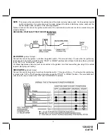
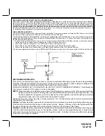
2 Pin Blue Connector :
Push-Button Programming Switch
Route the gray and black wires in the 2 pin connector from the previously installed push-button programming switch
to the control module and plug it into the mating blue connector on the side of the module.
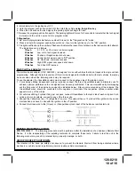
3 Pin Antenna/Receiver Connector:
(White Connector)
Plug the previously routed three pin connector from the antenna receiver assemble into the mating connector
of the control module. This connector supplies 12 volts, ground and RF data from the antenna receiver to the
remote start module. Be certain this connector is firmly seated making good contact to the control unit.
1. RF Programmable Features:
Feature Selection
1 Flash
2 Flash
3 Flash
4 Flash
Default
1 Run Time
5 Min.
10 Min.
15 Min.
20 Min.
10 Min.
2 Ign. 2 During Crank
Off
On
On
3 Light Output During Run Steady
Flash
Steady
4 Mode Select
Voltage
Tach
Tach
5 Voltage Level
> 0.5V B4 Start < 0.5V B4 Start
> 0.5
6 Trouble Shooting
Off
On
Off
7 Crank Time
0.8Sec
1.0 Sec
1.5 Sec
2.0 Sec
1.0
8 Gas/Diesel
Gas
Diesel 10
Diesel 15
Diesel 20 Gas
9 BS Output From Tx
Single Pulse Double Pulse
Single
Note: When setting feature #9 to operate as single pulse, the BS wire will output a single pulse before start and
while running if the transmitter button is pressed for 2 seconds. If set for double pulse the BS output will be a
double pulse before start and while running if the transmitter button is pressed for 2 seconds. This can be used
to unlock the vehicle doors when the consumer arrives at the vehicle if it is still running under control of the remote
start.
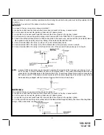
To program these selectable features:
1. Turn the ignition key to the ON position.
2. Press and release the program push-button switch 3 times.
3. Immediately turn the ignition key OFF, then back to ON.
4. Press and release the program push-button switch 2 times
5. Use the program push-button switch to advance to the feature that you want to change.
EXAMPLE
- If you need to
change programmable feature number 3, press and release the program push-button switch 3 times in succession.
The parking lights will flash 3 times confirming that selected feature 3 can now be programmed.
7. Press The Vehicle's Brake to change the selection of the programmable feature. If you are not sure what the setting
for any feature is, press the brake one time, the parking lights will flash once or twice, etc... indicating the features
setting.
NOTE:
Once you enter the feature-programming mode, do not allow more that 15 seconds to pass between steps,
or the programming will be terminated.
NOTE:
If the Glow Plug sense wire, Green/Yellow is connected, this wire will have priority over the setting of feature
#8.
2. Programming Tach Rate:
NOTE:
All applications require that tach be programmed.
The unit will not operate unless tach is programmed. If an attempt is made to start the vehicle via the remote start without
first programming tach, the unit will flash the parking lights 7 times indicating tach has not been learned and stored.
If the tach rate is not properly programmed to the specific vehicle, the unit may not realize that the vehicle is running
in certain instances and could re-engage the starter motor.
The Remote Car Starter will learn the tach rate of most vehicles single ignition coils, multiple coil packs, and or single
injector. To learn tach;
1. Turn the ignition key to the ON position.
3. Press and release the program push-button switch 3 times.


