


128-8210
11 of 16
11
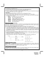
To test the integrity of this circuit:
1. With the driver's window in the down position, start the vehicle using the RF transmitter.
2. Reach inside the car and pull the hood release.
3. Raise the hood and confirm that the remote start unit shuts down.
If the unit fails this test, recheck your pin switch connection to the Gray/Black wire of the Audiovox Remote Start Unit.
W A R N I N G ! !
DO NOT RELEASE THIS VEHICLE TO THE CONSUMER UNTIL YOU CONFIRM THE
OPERATION OF THE HOOD PIN SAFETY SHUT DOWN FEATURE.
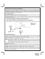
MANUAL SHUT DOWN / ENABLE CIRCUIT:
The intent of the manual shut down / enable circuit is to allow the vehicle operator to prevent operation of the Remote
Start Unit regardless of the RF transmitter operation.
To test the integrity of the manual shut down / enable circuit:
1. Place the control switch in the on (Closed To Ground) position.
2. Start the vehicle using the RF transmitter.
3. The vehicle should start and run under the control of the remote start unit.
4. Move the switch to the off (Open From Ground) position, the vehicle should shut off.
If the unit fails this test, recheck your enable switch connection to the Ground and the Black/White wire of the Audiovox
Remote Start Unit. If you have a plug in enable switch, check that the 2 pin connector is firmly seated in the mating
connector on the control module.
W A R N I N G ! !
DO NOT RELEASE THIS VEHICLE TO THE CONSUMER UNTIL YOU CONFIRM THE
OPERATION OF THE MANUAL SHUT DOWN / ENABLE FEATURE.
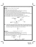
NEUTRAL START SAFETY TEST:
The intent of the neutral start switch is to prevent the vehicle from starting while the gear selector is in any position
other than Park, or Neutral. When installing a Remote Start Device, it is imperative that the Yellow Starter wire be
connected to the ignition switch side of the Neutral Start Switch. Consideration for the placement of a starter inhibit
relay is important as well, and should be connected to the ignition switch side of the Yellow Start Wire.
To test the integrity of the Neutral Start Safety Circuit:
1. Set the vehicle parking brake.
2. Block the drive wheels to prevent vehicle movement.
3. Temporarily disconnect the Brown/Black positive shut down wire from the vehicle's brake switch.
4. Sitting in the vehicle, start the engine using the vehicle's ignition key.
5. Step on the brake pedal and shift the gear selector into reverse.
6. Allow the transmission to shift. When you feel the engine pull, do not move the gear selector just turn the ignition
switch off. DO NOT attempt to remove the key.
7. Keeping the brake pedal depressed, activate the RF transmitter in an attempt to start the vehicle. The car should
not start.
8. Repeat the above test this time move the gear selector to the drive position. If the unit attempts to start, failing this
test, recheck your Yellow Wire's connection. This wire must be connected to the ignition switch side of the Neutral
Start Switch. If the vehicle you are working on does not have an Electrical Neutral Safety Switch, it will be
necessary to reconfigure the Remote Starts Wiring to accommodate this vehicle. The information concerning the
Mechanical Neutral Safety Switch provided below will help you to determine if the vehicle you are working on has
this type of safety switch and will provide alternate wiring methods to accommodate this situation.
W A R N I N G ! !
REMEMBER TO RECONNECT THE BROWN/BLACK WIRE TEMPORARILY
DISCONNECTED IN STEP 3.
DO NOT RELEASE THIS VEHICLE TO THE CONSUMER UNTIL YOU CONFIRM THE OPERATION OF
THE NEUTRAL SAFETY START FEATURE.


