background image

128-9310

3of 30

3

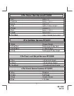
26 Pin Main Wiring Harness #1124302

1   Green/White 

Dome Light Output (-)

2   LT. Blue 

Ground While Running Output (-)

3   Black/White 

Horn Output (-)

4   Purple 

(+) Door Trigger input

5   Brown/Black 

(+) Inhibit/Shutdown To Brake Switch

6   DK. Blue/Black 

External Remote Start Trigger Input (-)

7   Orange/Black 

(-) Parking Brake Input

8   Green/Yellow 

Glow Plug Input

9   Brown 

(-) Door Trigger Input

10 Green/Orange 

Tachometer Input

11 DK Green 

(-) Instant Trigger Input

12 NC 

No Connection, Empty Cavity

13 LT. Green 

(-) Trigger Input

14 DK. Blue 

Channel 3 Trunk Release Output (-)

15 Green/Black 

Channel 4 Output (-)

16 DK.Blue/Red 

Channel 7 Output (-)

17 Black/LT.Green 

Pulse After Start Output  (-)

18 Black/Blue 

Pulse Before Start Output  (-)

19 Black/Red 

Pulse After Shut Down Output (-)

20 Black/Yellow 

Pulse During Crank Output (-)

21 LT. Blue/Black 

Channel 6 Output (-)

22 LT.Blue/Green 

Channel 5 Output (-)

23 Gray/Black 

(-) Inhibit/Shutdown To Hood Switch

24 Orange 

Start Inhibit Relay Control (-)

25 White/Blue 

(-) Headlight Activation Output

26 Orange/White 

N.O Start Inhibit Relay Control (-)

Содержание APS-997EC

Страница 1: ...Sensor Harness Page 19 Time Start Programming Information Page 19 Temperture Start Programming Information Page 19 DBI Port Information Page 19 Diesel Engine Setting Information Page 19 Diagnostics Ac...

Страница 2: ...f air bags or damage sensitive vehicle computers and electronics For technical support go to www avxtech1 com or call 1 800 225 6074 FCC COMPLIANCE This device complies with Part 15 of the FCC rules a...

Страница 3: ...DK Green Instant Trigger Input 12 NC No Connection Empty Cavity 13 LT Green Trigger Input 14 DK Blue Channel 3 Trunk Release Output 15 Green Black Channel 4 Output 16 DK Blue Red Channel 7 Output 17 B...

Страница 4: ...Pink Ignition 3 Common Contact 5 Purple Accessory 6 Red Battery 2 12V 7 Yellow Starter Output 8 Red Black Ignition 3 Normally Open Contact 1 Black Chassis Ground 2 White Red Parking Light Relay Input...

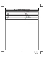
Страница 5: ...128 9310 5of 30 5 6 Pin Antenna Harness 1124293 1 Red 5 VDC 2 Green RX 3 Black Ground 4 Grey Valet Enable 5 Blue LED Cathode 6 Blue TX...

Страница 6: ...he input wire activating the alarm In addition the hood switch is required for the safety shut down of the remote start unit If the vehicle is being worked on this hood switch prevents the remote star...

Страница 7: ...t as well as the ignition 1 and ignition 2 relays 3 GREEN Wire Ignition 2 Output Connect this wire to the ignition 2 wire from the ignition switch This wire will show 12 volts when the ignition key is...

Страница 8: ...tch is turned to the start crank position only This wire will have 0 volts in all other ignition switch positions NOTE This wire must be connected to the vehicle side of the starter cut relay when use...

Страница 9: ...sensor s operation until the Remote Start unit shuts off B Additional Ignition Output Some vehicle s may require more than three ignition outputs to start and keep the vehicle s engine running If this...

Страница 10: ...e uses a 12 VDC horn switch then connect the black w white trace wire to terminal 86 of a 30Amp automotive relay and connect relay terminal 85 to a fused 12 VDC battery source Connect relay terminal 8...

Страница 11: ...glow plug output also activates The remote start sees the green yellow with positive voltage and waits for this to go inactive drop to 0 volts before activating the starter motor If this wire is not...

Страница 12: ...300 mA switched output whenever channel four of the receiver is accessed Pressing the pre programmed transmitter button s will provide a 1 second pulse to channel four This is a low current output and...

Страница 13: ...put is selectable and can function as described in feature selection of bank 3 feature 22 20 Black w Yellow trace Wire Ground Output During Start Crank The Black w Yellow Trace wire will provide a 300...

Страница 14: ...e relay provided Connect terminal 85 red wire of the relay to an ignition wire in the vehicle that is 12 volts when the ignition switch is turned to the on and start positions and off when the key is...

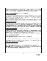
Страница 15: ...the starting circuit of the vehicle 4 Pin Additional Harness Parking Light Flasher I O Siren Ground Part 1284301 1 Black Chassis Ground Connect the Black wire to a known vehicle ground source or to a...

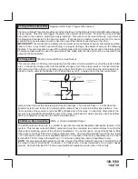
Страница 16: ...l the drivers door unlock relay and the Red Black will be used to control the unlocking of all other doors 3 Wire Ground Switched Door Lock Circuits In this application the Red wire of the door lock h...

Страница 17: ...tory Switches 12 Volts Connect to Fused 12 Volt Source If Factory switches Ground Connect To Ground 87a 87 30 86 85 Fused 12 Volt Source Factory Unlock Relay 3 Wire Positive Switched Door Locks For th...

Страница 18: ...l components which may include relays fixed resistor a door lock interface or a data module You can search the vehicle www avxtech1 com Flash It com for vehcile specific information or contact our tec...

Страница 19: ...tart timer within 10 seconds of turning off the ignition switch activate the RF command to start 2 times Press the start button four times The lights will flash and the siren will chirp 4 times Indica...

Страница 20: ...ule and have determined that a tach signal is available for the vehicle you are connecting to The unit will look at the DBI data port for the tach signal If the vehicle fails to start or the unit flas...

Страница 21: ...Start Unit regardless of the RF transmitter operation To Enter The Remote Start Override Mode 1 With the system disarmed unlocked and the ignition switch off Press and Hold the pushbutton switch locat...

Страница 22: ...BROWN BLACK NEUTRAL SAFETY WIRE TEMPORARILY DISCONNECTED IN STEP 3 MECHANICAL NEUTRAL SAFETY SWITCH CONSIDERATIONS Mechanical neutral safety switch configurations differ slightly in that they do not o...

Страница 23: ...ETHOD 1 87a 87 30 85 86 To Fused 12 Volt Battery Source Ignition Key In Sense Wire Closes With Key In Cylinder 1N4002 Diode 1N4002 Diode Connect To Negative Remote Start Safety Shut Down Wire Drivers...

Страница 24: ...n switch is also used for an alarm trigger input be certain to use the dual diode set up shown earlier in this manual AFTER THE CONNECTION OF THE NEUTRAL START SAFETY WIRE AS INDICATED IN ANY OF THE P...

Страница 25: ...he adjustment screw counter clockwise COMPLETING THE INSTALLATION After you have confirmed the operation of the Remote Start unit and tested all the safety features of the system 1 Mount the control m...

Страница 26: ...2 etc then use the lock button of the transmitter to select the feature setting Example to set passive arming 1 Turn the ignition key to the on position 2 Press and release the valet programming switc...

Страница 27: ...4 Chirps 5 Chirps 6 Chirps 1st DoorL UL 500 mS 3 5 Sec 500mS L Dbl U L Dbl L 500mS UL Dbl L Dbl UL 500mS 350mS ul 2nd Accy Lock Auto Lock On Auto Lock Off 3rd Accy UL Auto UL Dr Auto UL All Auto UL O...

Страница 28: ...5 Press the pushbutton switch five times to advance to features 5 Input Check then use the lock button of the transmitter to select three chirps DBI Tach 6 To exit the programming mode turn the ignit...

Страница 29: ...ime Note When averaging the engine must be started 4 times with the key to be effective 15th R S Shock Shunt Unit Clear Shunt R S Cycle Shunt From Tx 16th Turbo Select Off 3 Mins 5 Mins 10 Mins 17th O...

Страница 30: ...ut When Armed Output White Blue Headlight Activation Output LT Green Trigger Additional Sensor Trunk Orange White Ground When Disarmed Output No Connection Empty Cavity To Mating Connector Of Shock Se...

Страница 31: ...128 9310 31of 30 31...

Страница 32: ...128 9310 32of 30 32...

Отзывы: