


30
3.3 Schematic overview of the expansion system
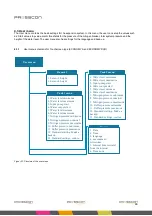
Figure to Figure give a schematic overview of the VERNIT and HORNIT expansion systems. They show how all the
components within the system are communicating with each other. They also give an indication of what roll the
expansion system has in combination with the central heating system.
3.3.1 VERNIT 2.0 -30.0 N2(i) system
Figure 16. VERNIT 2.0 – 30.0 N2(i) system overview
PRESSCON
Buffer tank
Control
(PRESS-control minimal)
Boiler
Notification
device
Nitrogen
generator
Water
pump
Pressure
Sensor 2
Pressure
Sensor 1
CAN-bus
Analogue water level
Analogue nitrogen pressure
External generator
Alarm notifier
Boiler on / off
Water
inlet
Water outlet
Sensor offset
± 9 meter
Nitrogen
inlet valve
25 mBar
Mechanical pressure
release valve 20 mbar
(Nitrogen outlet valve)
Valve control
Nitrogen pressure
Hot water
buffer tank
Compressor
Drainvalve on/off
Compressor status
Compressor on/off
Nitrogen pressure
vessel (Optional)
Pressure
Sensor 5/6
O
2
Touchscreen
Содержание HORNIT N2
Страница 2: ...2...


