background image

8

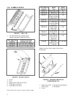
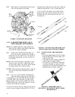
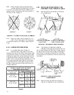
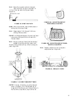
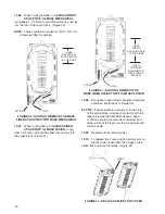
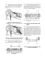
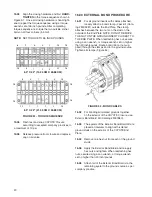
FIGURE 15A - ATTACH "L" BRACKET–

FRONTAL VIEW

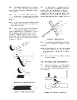
FIGURE 15B - ATTACH "L" BRACKET–SIDE VIEW

7.02


Remove the protective vinyl tape applied to  


LOCK-TAPE Sealant in Paragraph 4.08.

7.03


Place the cable into the End Plate as close to  


the assembly location as possible. Mark it 

1/4-1/2" (.64-1.27 cm) from the outside surface of the 
End Plate. Apply vinyl tape over the remaining LOCK-
TAPE Sealant. 

Do not apply vinyl tape in the seal 

area.

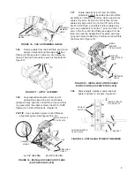
7.04


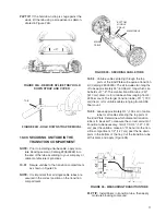
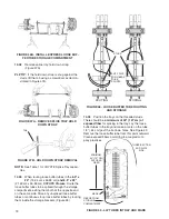
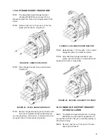
Use the strength member cap on the "L"  


bracket as a guide for trimming the strength 

member. (Figure 16)

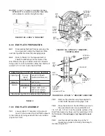
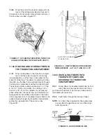
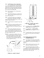
PLP TIP:

  A long "L" bracket is available (Catalog 

#80805431) for bonded loose buffer tube cable 
with a dielectric central strength member.

FIGURE 14B - LONG "L" BRACKET

6.00  END PLATE PREPARATION

6.01


Disassemble the End Plate by removing the  


two long bolts holding the three End Plate 

sections together. Remove the packaging plugs.

6.02


Refer to Table 2 for the measurement of   


sheath to extend beyond the inside of the 

End Plate for the type of cable and bond connector 
being used. For all non-metallic cables the sheath will 
extend 3/4" (1.90 cm) inside the End Plate. 

Cable Positions In COYOTE Closure End Plate

Cable Type

If using 

Bond 

Connectors

Length of Sheath 
Inside End Plate (cm)

Dielectric

3/4" (1.90)

Metallic

RAYCHEM* 1-1/4" (3.18)

AT&T*

Total 1-3/8" (3.47) = 
5/8" (1.57)  
3/4" (1.90) sheath

*See Accessory Kits for additional bond hardware

TABLE 2

7.00  END PLATE ASSEMBLY

7.01


Loosely attach "L" brackets to the ground  


insert on the inside of the End Plate adjacent 

to the cable ports being used with the nut provided. 
(Figure 15 A & B)

INTERNAL 
GROUND
INSERT

BOLT
HEAD-
TOP

EXTERNAL 
GROUND
INSERT--
DOUBLE-NUTTED

"L" BRACKET

BOLT-
BOTTOM

STRENGTH
MEMBER
CAP

"L" BRACKET

BOLT
HEAD-
TOP

BOLT-
BOTTOM

INTERNAL 
GROUND
INSERTS
FOR EACH
PORT

STRENGTH
MEMBER
CAP

MAIN 
CABLE 
PORT 
ENTRY

Содержание COYOTE 80805112

Страница 1: ...LICATION 6 7 5 INTERNAL BOND PROCEDURE 7 6 END PLATE PREPARATION 8 7 END PLATE ASSEMBLY 8 9 8 UNITUBE PREPARATION 10 9 INSTALLING TRANSITION COMPARTMENT FOR SINGLE TUBE CABLE 10 11 10 SECURING UNITUBE...

Страница 2: ...LOSURE DIMENSIONS CM 80805258 6 0 x 22 15 24 X 55 88 80805259 8 5 x 22 21 59 X 55 8 1 2 3 4 PLP Catalog Number Splice Tray Splice Capacity 80805110 Single Fiber Tray 36 80805509 Blank Tray 36 80805514...

Страница 3: ...Tape not 4 1 2 2 5 6 1 2 2 3 5 6 4 PLP Catalog Number Description 80805105 Three Section Six Port End Plate Kit 80806037 3 4 plugs 2 80806180 7 8 plugs 2 8003371 Future Cable Port Kit for 7 8 port 56...

Страница 4: ...t 80805293 Transport Tube Kit 6 per kit 80805107 Strength Member Bracket Kit 2 per kit 80805431 Long Strength Member Bracket Kit 2 per kit 8003280 Transition Tube Kit 8003281 External Bond Clip Kit 2...

Страница 5: ...8 2 22 cm diameter B 3 4 1 90 cm diameter FIGURE 7A DIAGRAM OF SIX PORT END PLATE A 1 2 54 cm diameter B 1 1 4 3 18 cm diameter FIGURE 7B DIAGRAM OF FOUR PORT END PLATE A A B B A A B 6 0 X 22 15 24 c...

Страница 6: ...eck whether the LOCK TAPE Sealant wrap is the proper diameter to ensure a water and air tight seal Figure 9 For the Six Port End Plate the orange colored end is used to measure cables entering the 7 8...

Страница 7: ...check gauge LOCK TAPE Sealant must be reapplied It is acceptable to reapply the original LOCK TAPE Sealant Figure 13 SLOT 4 04 Using the provided Emery Cloth thoroughly scuff the cable sheath for 5 1...

Страница 8: ...ree End Plate sections together Remove the packaging plugs 6 02 Refer to Table 2 for the measurement of sheath to extend beyond the inside of the End Plate for the type of cable and bond connector bei...

Страница 9: ...insert ports at this time Future cable entry ports will t in only the 7 8 ports of the Six Port End Plate and different future cable entry ports are available for both the 1 ports and the 1 1 4 ports...

Страница 10: ...IGURE 21 CORRECT END PLATE ALIGNMENT 7 10 Apply vinyl tape to the remaining 1 4 1 2 64 1 27 cm Paragraph 7 03 of exposed LOCK TAPE Sealant on the cable outside the End Plate 8 00 UNITUBE PREPARATION 8...

Страница 11: ...tion compartment 1 2 1 27 cm past the tie down ports in the bottom of the tray Cut the transition tube at this mark and apply Figure 26 FIGURE 26 MEASURING TRANSITION TUBE PLP TIP Install bers in tran...

Страница 12: ...m and trays 1 8 of the 8 5 x 22 21 59 cm x 55 88 cm via transport tubes Wrap the continuous loop and the bers not being spliced until all bers are stored in the transi tion compartment For cut cables...

Страница 13: ...5 Secure all transport tubes with the felt tape applied to the inside tie down holes in the transition compartment with two of the tie wraps pro vided Figure 31 FIGURE 31 SECURE TRANSPORT TUBES PLP TI...

Страница 14: ...plice block see Figure 37B 13 00 SECURING TRANSPORT TUBES AND ROUTING FIBER IN SPLICE TRAYS 13 01 There are six types of splice trays available for the COYOTE Closure The single ber trays are designed...

Страница 15: ...tors and sili cone caulk Place Splice Count Label on cover to identify bers spliced On the back of both trays slots are provided to aid in the removal of splice protectors or connectors Figure 39 FIGU...

Страница 16: ...he hinges on the splice tray and snap into place Figure 42 FIGURE 42 REPLACE SPLICE TRAY COVER 13 06 When routing the ber in the MASS FIBER SPLICE TRAY for MASS MECHANICAL route bers 1 1 2 times aroun...

Страница 17: ...6B to the torque bar bracket on the bottom of the End Plates with the bolts provided Make sure the side of the torque bar labelled 3 Section End is nearest the Three section End Plate The torque bars...

Страница 18: ...47A PLP TIP If the hold down strap is snug against the studs lift the tab using a screwdriver as demon strated in Figure 47B FIGURE 47A REMOVE SPLICE TRAY HOLD DOWN STRAP FIGURE 47B HOLD DOWN STRAP RE...

Страница 19: ...branch cable is being spliced More room in the storage compartment is required for the storage of slack buffer tube 14 06 Follow Paragraph 4 01 for cable opening measurements 14 07 Separate the buffe...

Страница 20: ...Plate 16 04 Remove one hex nut from each of the ground studs 16 05 Apply the Exterior Bond Braid and re apply hex nuts and tighten When reattaching hex nuts secure using a can wrench or torque wrench...

Страница 21: ...le racking or hand hole racking 18 02 Remove one hex nut from each of the two upper ground inserts 17 00 STRAND MOUNT PROCEDURE 17 01 The Adjustable Aerial Hanger Bracket Catalog 8003325 can be used f...

Страница 22: ...the Ts on top of the Manhole Support Brackets until the support bar is centered over the COYOTE Closure PLP TIP Cable tie the support bar to the rack steps for added security 19 00 BURIED INSTALLATIO...

Страница 23: ...23...

Страница 24: ...24 SP2822 5 P O Box 91129 Cleveland Ohio 44101 440 461 5200 www preformed com email inquiries preformed com...

Отзывы: