background image

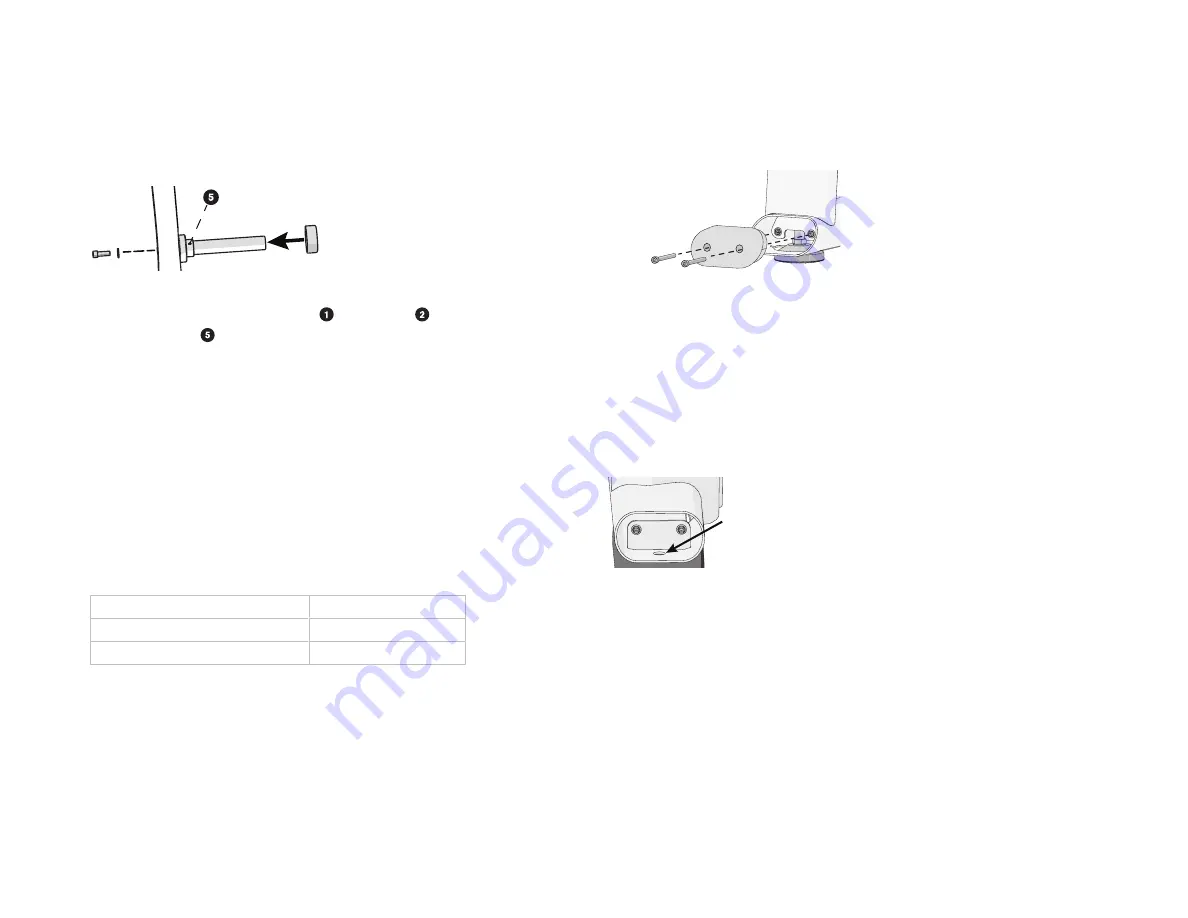
Attach weight storage horns

1.

Insert the weight horn into the hole in the rear upright frame until it stops

(Figure 17).

Figure 17 

2.

Secure the weight horn using a bolt   and washer   .

3.

Place a set screw   into the horn assembly and tighten.

4.

Push the storage horn bumper into the weight horn with its wide side facing

outward. If needed, use a weight plate to push the bumper against the

equipment frame.

5.

Repeat this procedure to attach the other weight horns.

Stabilize the equipment

Once you have assembled the equipment, test its stability by pushing down on

each corner. If the base frame rocks or wobbles, you need to adjust the feet to

stabilize it.

To stabilize the equipment:

1.

Locate the round, adjustable feet on the bottom of the equipment frame.

2.

Using a 19 mm open-end wrench, turn the positioning bolt to the left or right

to level the equipment.

To move the adjustable foot ...

Then turn the bolt ...

Upward

To the right

Downward

To the left

3.

Continue to test the corners of the equipment and readjust the feet as

needed.

4.

When the equipment is stable, re-tighten the jam nut with an 18 mm open-

end wrench to 600 in-lb (67.79 N-m).

5.

Insert the frame end cap and secure it using two M6 × 60 mm socket head

cap screws. Tighten the screws to 10 in-lb (1.12 N-m) of torque (Figure 18).

Bolt equipment to the floor

Precor recommends that the strength equipment be bolted down at all anchoring


points. Bolting is made possible by removing the end caps at the frame base and


exposing the mounting holes that accommodate the bolts (see the accompanying


figure). Replace end caps when bolting is complete.

As floor materials vary, it is important that you consult a licensed contractor to


advise you on proper bolting techniques and appropriate fastener types.

Standards occasionally change or are updated. Precor recommends that you keep


apprised of your local industry standards. Precor shall not be held liable for failure


to properly bolt the strength equipment to the floor.

Figure 18 

7

Содержание Discovery Series

Страница 1: ...Discovery Series Plate Loaded Squat Machine 624 Assembly Guide ENGLISH ...

Страница 2: ......

Страница 3: ... to use it Locate the equipment at least 40 inches 1 meter away from walls or furniture on either side of the equipment and 40 inches 1 meter away from objects behind or in front of the equipment Assemble the equipment on a solid flat surface so that it remains level and stable Required tools Torque wrench Rubber mallet 18 mm open end wrench 19 mm open end wrench Counter weight Cable arm Center fr...

Страница 4: ...3 mm black 6 Flat washer 12 2 x 30 mm 6 End cap 4 Button head cap bolt M8 x 15 mm 5 Flat head bolt M12 30 mm 4 Hex key 8 mm 2 Hex key 10 mm 1 Flat head hex screw M8 x 20 mm 6 Component Quantity Flat head hex bolt M12 x 70 mm 2 Button head bolt M10 x 25 mm black 6 Socket head bolt M8 x 25 mm 2 Flat washer 9 x 16 mm 7 TPU rubber bumper washer 4 Button head bolt M10x16 mm 2 Flat washer M10 x 20 mm 2 ...

Страница 5: ... 2 3 Attach the center frame to the base frame using two bolts and washers and to the rear upright using two bolts and washers 4 Fully tighten all bolts 5 In the center frame bracket position the shoulder frame support pivot to align the bracket and frame openings Slide the short axle through the base of the shoulder frame support and attach the shoulder frame support using two bolts and two end c...

Страница 6: ...istant to hold it level while you slide the axle through the bracket and secure it using two bolts and two washers 4 Fully tighten all bolts to 65 ft lb 88 N m Attach the shoulder frame 1 Slide the shoulder pad assembly tube onto the shaft Figure 5 2 Secure it using one bolt and one end cap Figure 5 3 Repeat Steps 1 and 2 to attach the other shoulder pad assembly tube Fully tighten the bolts 4 Rec...

Страница 7: ...the height adjustment assembly bottom rod end and position it inside of the weight arm bracket Figure 11 20 19 Figure 11 2 Slide the selector tube pin through the brackets bumpers rod end and secure it with the bolt and washer 3 Repeat Steps 1 and 2 to attach the height adjustment assembly top rod end to the shoulder frame Figure 12 When assembly is complete check to ensure that the Adjustable Hei...

Страница 8: ... Figure 13 b Continue this process until the pop pin does not release with the handle depressed NOTE In rare cases it may be necessary to adjust the nut in turn increments to meet both retest checks Attach foot plate 1 Position the foot plate onto the base frame 2 Secure the plate using two bolts Figure 14 Fully tighten the bolts Figure 14 Attach Weights Attach weight arm horns 1 Slide the weight ...

Страница 9: ... turn the bolt Upward To the right Downward To the left 3 Continue to test the corners of the equipment and readjust the feet as needed 4 When the equipment is stable re tighten the jam nut with an 18 mm open end wrench to 600 in lb 67 79 N m 5 Insert the frame end cap and secure it using two M6 60 mm socket head cap screws Tighten the screws to 10 in lb 1 12 N m of torque Figure 18 Bolt equipment...

Страница 10: ...DPL Squat Machine 624 Assembly Guide P N CW39176 112 ENU 2019 Precor Incorporated 16 May 2019 ...

Отзывы: