
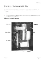
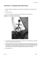


9.55 Treadmill
Page 21
Procedure 5.3 - Troubleshooting the Speed Sensor
Note:
The speed sensor is a hall effect sensor that emits a pulse when a flywheel lobe passes between
it’s transmitter and receiver. The speed control circuit processes the pulse train emitted by the
speed sensor. The speed sensor signal is a real time representation of the operating speed of
the treadmill. The speed control circuit compares the real time speed (speed sensor output) with
the speed that it expects the treadmill to be operating at and acts accordingly to control treadmill
speed or initiate an error code sequence, if necessary. Typically, if a problem exists with the
speed sensor the drive motor will operate (perhaps only briefly) before a speed related error
occurs (errors 20-26).
1.
Set the treadmill circuit breaker in the “on” position. Using a DC voltmeter, measure the
voltage between terminal 3 of J2 (green wire) and terminal 4 of J2 (black wire) on the lower
logic PCA. Slowly, rotate the drive motor flywheel. The voltage should read approximately 5
Vdc when a flywheel lobe is between the speed sensor “legs” and approximately 0.25 Vdc
when a flywheel lobe is not between the speed sensor “legs”.
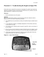
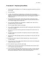
Diagram 5.3 - Speed Sensor Mounting
2.
If the voltages in step 1 are correct, go to step 5. If the voltage in step 1 is 0 Vdc or
significantly low when a flywheel lobe is between the speed sensor “legs’, continue with step
3.
3.
Measure the voltage between terminal 1 of J2 (red wire) and terminal 4 of J2 (black wire) on
the lower PCA. The voltage should read approximately 5 Vdc.
Flywheel
Speed
Sensor
Содержание 9.55
Страница 34: ...9 55 Treadmill Page 1 34 Page 34 15 Re install the hood 16 Check treadmill operation per Procedure 3 ...
Страница 43: ...9 55 Treadmill Page 43 Wiring Diagram 7 1 9 55 version 1 ...
Страница 46: ...9 55 Treadmill Page 1 46 Page 46 Wiring Diagram 7 4 9 55 120 Vac version 2 ...
Страница 47: ...9 55 Treadmill Page 47 Wiring Diagram 7 5 9 55 240 Vac version 2 ...
Страница 48: ...9 55 Treadmill Page 1 48 Page 48 Block Diagram 7 6 9 55 120 Vac version 2 ...
Страница 49: ...9 55 Treadmill Page 49 Block Diagram 7 7 9 55 240 Vac version 2 ...


