


9.55 Treadmill
Page 19
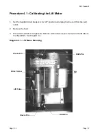
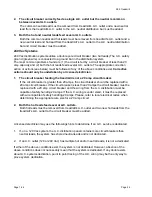
4.
Insert the treadmill’s line in the AC outlet and set the circuit breaker in the “on” position. Set
the treadmill in the manual program and press the
LIFT
▲
key. If the lift motor operates
normally, test treadmill operation per Section 3. If the lift motor still does not operate, retest
the lift fuse per steps 2 & 3. If the fuse is open again, continue with step 13. If the fuse is
good continue with step 5.
5.
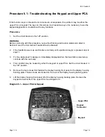
Connect an AC voltmeter between terminals 1 & 3 of the J5 connector. See Diagram 5.2.
Set the treadmill in the manual program and press the
LIFT
▲
key. The AC voltmeter
should read AC line voltage (either 120 Vac or 240 Vac) and the
UP
LED should illuminate
.
Note that the AC line voltage reading will only be present before an error condition is
displayed.
6.
If the F2 fuse is good and the
UP
LED illuminates and the AC voltmeter does not read the
presence of AC line voltage replace the lower logic PCA per Procedure 6.3.
7.
If the
UP
LED does not illuminate and the display indicates that the lift should be moving
upward, replace the upper PCA per Procedure 6.8.
8.
If the AC voltmeter reads the presence of AC line voltage and an error 40 is displayed, go to
step 10.
9.
If the AC voltmeter reads the presence of AC line voltage and an error 42 is displayed,
continue with step 11.
10. Set the treadmill’s circuit breaker in the “off” position and remove the AC line cord from the
AC outlet. Remove the lift motor connector from the J5 connector on the lower logic PCA.
Visually. inspect the lift motor connector for broken or improperly crimped connections.
Using an ohmmeter, read the resistance between terminals 1 & 4 and between terminals
3 & 4. Both readings should be approximately 15
Ω.
If either reading is open or very high
resistance, replace the lift motor per Procedure 6.1.
11. Set the treadmill’s circuit breaker in the “off” position and remove the AC line cord from the
AC outlet. Remove the lift motor connector from the J1 connector on the lower logic PCA.
Visually inspect the lift motor connector for broken or improperly crimped connections.
Using an ohmmeter, measure between terminals 1 & 3, 1 & 2 and 2 & 3 of the lift motor
connector. Terminals 1 and 3 should read approximately 1 K
Ω
. The sum of the two readings
between terminals 2 & 3 and 1 & 2 should total approximately 1 K
Ω.
If either reading is open
or very high resistance, replace the lift motor per Procedure 6.1.
12. If you have performed all of the procedures above and have been unable to correct the
problem, call Precor customer service.
13. Set the treadmill’s circuit breaker in the “off” position and remove the AC line cord from the
AC outlet. Remove the lift motor connector from the J5 connector on the lower logic PCA.
Visually inspect the lift motor connector for broken, frayed or improperly crimped
connections. Using an ohmmeter, read the resistance between terminals 1 &4, 3 & 4 and
1 & 3. The readings should be approximately 15
Ω,
15
Ω
and
30
Ω,
respectively
.
If the
reading is significantly low, replace the lift motor per Procedure 6.1.
Содержание 9.55
Страница 34: ...9 55 Treadmill Page 1 34 Page 34 15 Re install the hood 16 Check treadmill operation per Procedure 3 ...
Страница 43: ...9 55 Treadmill Page 43 Wiring Diagram 7 1 9 55 version 1 ...
Страница 46: ...9 55 Treadmill Page 1 46 Page 46 Wiring Diagram 7 4 9 55 120 Vac version 2 ...
Страница 47: ...9 55 Treadmill Page 47 Wiring Diagram 7 5 9 55 240 Vac version 2 ...
Страница 48: ...9 55 Treadmill Page 1 48 Page 48 Block Diagram 7 6 9 55 120 Vac version 2 ...
Страница 49: ...9 55 Treadmill Page 49 Block Diagram 7 7 9 55 240 Vac version 2 ...


