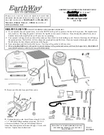
SB52 & SB52GY Assembly Instructions
Attach Control Cable Assembly by passing a 2-1/2”
Round Head Bolt through Cable Assembly and Handle.
Secure with Wing Nut.
Attach the Leg Stand to the outside of Hopper
Supports using 1/4” x 1-3/4” Carriage Bolts and
Wing Nuts.
ASSEMBLY TIP: Loosely
tighten nuts and bolts at
first. Fully tighten when the
unit is completely
assembled.
Carriage Bolt
(6 Required)
(7 Required)
Settings are made by pressing
down on the Calibration Indicator
button and setting to desired
number on the Control Cable
Assembly.
USING YOUR SPREADER
* TO OPEN
- Push the Control Lever
forward until it stops against button.
* TO CLOSE
- Pull the Control
Lever back toward Operator.
See Application chart for
setting information
.
AFTER EACH USE: Wash unit thoroughly let dry. Lubricate
moving parts, including slide plate, axle and upright shaft.
MAINTENANCE INSTRUCTIONS
CAUTION:
CARE MUST BE TAKEN WITH ANY WEED
KILLER, PESTICIDE, OR COMBINATION
PRODUCT.
THEY CAN BE HARMFUL TO OTHER PLANT
LIFE IN THE YARD.
Attach Handle to Leg using 1/4” x 1-3/4”
Carriage Bolts and Wing Nuts.
ASSEMBLY HARDWARE REQUIRED
1/4“ Wing Nut
1/4” x 1-3/4”
Carriage
Bolts
Leg Stand
1/4” x 1-3/4”
Carriage Bolt
Wing Nut
Control Cable
Assembly
1/4” x 2-1/2”
Round Head
Bolt
Handle
Wing Nut
Top View
Lever Control
Calibration Indicator Button
Setting Numbers
2-1/4” Round Head Bolt
(1 Required)
STE
P
1
Wing Nuts
T
2
S
EP
STEP
3
Handle


