10
PM-1440E-LB 11-13-17 V1
Copyright © October 2017 Quality Machine Tools, LLC
SPINDLE SPEEDS
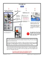
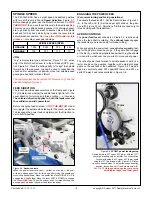
The PM-1440E-LB has an eight-speed headstock gearbox
with two shift levers,
LH
and
Speed Selection
, Figure 3-1.
Before changing speed, use the Motor Control lever to
STOP
THE MOTOR
, then move the shift levers to the desired setting.
This may need a little patience because it is not always possi-
ble to go directly from one mesh to another. Move the spindle
back and forth by hand while trying to ease the lever into its
detent (meshed) position.
Don’t use the JOG button in this
process
— this may cause gear damage.
FEED DIRECTION
The lever below the speed selectors on the front panel, Figure
3-1 (3) determines whether the saddle feed is right to left — the
usual direction for turning and thread cutting — or reversed.
The selected direction applies to both the leadscrew and
the saddle/cross-slide power feed
.
Before changing feed direction,
STOP THE MOTOR
. Hand-
turn (joggle) the spindle while feeling for the mesh, as above.
To disengage the power feed completely, set the Direction le-
ver to its mid-position.
SPINDLE SPEED (RPM)
H RANGE
1255
2000
755
460
L RANGE
190
300
115
70
JOG
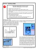
"Jog" is momentary-type push-button, Figure 3-1 (8),
active
only if
the Motor Control lever is in the mid-travel (OFF) posi
-
tion, Figure 3-2. Press the button briefly to "nudge" the spindle
forward by a few degrees. Jog can be used to reposition the
chuck and/or workpiece, especially when low spindle-speed
gearing makes hand rotation difficult.
The control system can be rewired for "Reverse Jog", see the
electrical diagram, Section 5.
ENGAGING THE POWER FEED
(For normal turning and facing operations)
To activate the feed shaft: 1. Set the Direction lever, Figure 3-1
(4), to the left, and; (2) Set the upper right knob on the gear
-
box to
N
, Figure 3-1 (9). Selections
1-2-3-4
are used only for
thread cutting with the leadscrew).
APRON CONTROLS
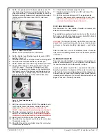
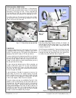
The
power feed lever
on the apron, Figure 3-4, is active only
when the feed shaft is rotating. The
split-nut lever
engages
the leadscrew, and is used only for thread cutting).
When engaging the power feed,
move the lever gently
, feel-
ing for the gears to mesh as you go. If the gears don’t engage
at the first try, use the appropriate handwheel to jog the saddle
or cross-slide, whichever one you wish to move under power.
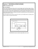
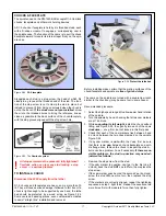
The rate of power feed relative to spindle speed is set by se-
lector knobs on the gearbox, together with external change
gears on the end face of the headstock, Figure 3-5. Two pair-
ings are commonly used: 30T upper/60T lower, and 60T up
-
per/60T lower. Feed rates are listed in Figure 3-6.
Figure 3-4
Apron controls
When the power lever is neutral — neither up or down — the pow-
er feed is disengaged. Test for this by gently turning the saddle and
cross-slide handwheels. Move the power feed lever RIGHT & UP to
engage the
Saddle
feed. Move the lever LEFT & DOWN to engage
the
Cross-slide
feed. The split-nut lever, used for thread cutting, can
be engaged only when the power feed lever is neutral.
Figure 3-5
30T/60T power feeding setup
Shown here are 30T upper, 60T lower, with the 127T
center gear acting only as an idler. The other option
for power feeding is 60T upper, 60T lower, again
using the 127T gear as an idler, Figure 3-6. Dimen-
sions are wrench sizes. To adjust the support casting
position, loosen hex nut (1) and clamp screw (2).
For U.S. TPI thread cutting use the same setup,
with different upper and lower gears.
19 mm
17 mm


