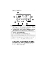
PRAXSYM DB-12 Скачать руководство пользователя страница 7

2.0  Operation  


2.1 Battery Charging 


The transmitter is fully operational while the batteries are being 
charged. Charging can occur whether or not the unit is powered on. 


When “batt low” appears in the battery icon, the battery life is nearing 
its end.  The transmitter will shut down soon.  Connect the AC/DC 

adapter (12 V /1.5 A) to the unit’s CHARGE jack.  Plug the adapter into 

a wall outlet.  An internal battery charger will control and terminate 
the charging of the 6 NiMH cells within each unit.  When beginning a 

charge cycle with batteries which have been completely depleted, 

allow about two and a half hours for a full charge to be restored.  A 
top-off charge is recommended immediately before use for maximum 

battery life.  


A flashing red LED indicates a precharge state. Usually it will flash  

for a few moments and then enter a fast charge state, indicated by a 

solid red LED.  The precharge state may last up to a few hours with 
drained batteries and indefinitely if one or more cells have failed.  All 

cells must be replaced in the latter case.  When the LED turns green, 

the batteries are fully charged and enter trickle charge mode 
indefinitely. Fully charged batteries will give six to eight hours of use.   

Also, the battery icon on the display will be completely darkened.  If 
the AC/DC adapter is left connected to the transmitter, the charger 

will initiate a new charge cycle once the batteries have discharged.  

This will occur continually.  Unless the transmitter is in operation, it is 
not recommended to leave the AC/DC adapter connected for more 

than 24 hours. 


Though designed for many recharge cycles, the batteries are user 

replaceable. Replace the batteries every 2-3 years. Use only 
Energizer® NH15 AA NiMH rechargeable batteries, as supplied 

originally. The internal charge circuit will only work with NiMH 

rechargeable batteries. Attempting to charge other AA battery types 
such as Alkaline or Lithium Ion will result in damage to the 

transmitter.   


Do not store the transmitter with discharged or failed batteries. 

Discharged NiMH batteries can leak acid causing damage to the 

transmitter. 

Содержание DB-12

Страница 1: ...CW Transmitter User s Manual...

Страница 2: ...terial defect In no case shall PRAXSYM s liability for breach of warranty exceed the purchase price of the items in question PRAXSYM s liability on any claim of any kind for any loss connected with or...

Страница 3: ...Table of Contents...

Страница 4: ...isplay The transmitter also contains a USB interface enabling the user to control the transmitter remotely The transmitter can be powered using the internal 6 AA rechargeable batteries for 6 hours of...

Страница 5: ...E 1 3 Items Supplied D C A B Item Description A CW Transmitter With 6 Internal NiMH AA Batteries B 12V 1 5A AC DC Supply C Power Cord D USB Cable E Flash Drive Users Manual Driver Software...

Страница 6: ...smitter C D E F G Item Description A Channel 1 Output N Type Connector B Channel 2 Output N Type Connector C Battery Charger Status LED D Battery Charge Jack E USB Port F LCD Touchscreen Display G Fro...

Страница 7: ...and indefinitely if one or more cells have failed All cells must be replaced in the latter case When the LED turns green the batteries are fully charged and enter trickle charge mode indefinitely Ful...

Страница 8: ...creen pressing the SEL Select button toggles between frequency amplitude and step size The arrow keys change the values of the selected option On applicable transmitter models touching the listed freq...

Страница 9: ...t key will modify the scan settings Selecting Scan Order allows the user to choose which Setups will be used in the scan AB ABC ABCD Selecting Dwell Time allows the user to select the duration at whic...

Страница 10: ...cable screens Also the same as the OK touch screen button UP DOWN ARROWS Adjust frequency amplitude or step size of highlighted channel in the main screen using the arrows Adjustments to frequency are...

Страница 11: ...D A C Item Description A On Off B Numerals 0 9 C Select D Up Down Arrows Plus Minus Signs E Lock Decimal F Menu B F E 2 4 Keypad Definition Continued...

Страница 12: ...reen the active channel band is noted at the top Continuing to touch the tabs will cycle through the channel Setups B Frequency Amplitude and Step size for both channels may be controlled using the SE...

Страница 13: ...allow for setting of Frequency Amplitude and Step Size Within the Channel Setup options Setups and Scan Mode are also configured Display Settings contains user selectable parameters for the duration o...

Страница 14: ...port assigned by PC operating system Local echo ON Select line feed LF after carriage return CR when receiving The settings may be found in various places depending on the terminal emulation software...

Страница 15: ...ansmitter 3 2 Commands Commands may be sent in lower or upper case All commands should be followed by CR CR represents ENTER Spaces are represented by underscores _ Note The equal can be replaced with...

Страница 16: ...yyyy Sets the channel spacing in MHz Example ST 0 0125 12 5 kHz Channel Spacing SCANSU_X_YYYY_ZZ z Scan Setup where X is 1 or 2 the physical channel being set up for scanning YYYY is either AB ABC or...

Страница 17: ...NOT SET UP FOR THIS CHANNEL BAND_X Assign band to current CH where X is 1 through 4 one of the internal calibrated bands The band s parameters are loaded into the setup previously selected by the CH...

Страница 18: ...n MHz See FR for example ST Returns the synthesizer step size setting in the form X yyyy MHz Example 0 0100 AMP Returns the current output amplitude in the form XX y dBm for the current channel Exampl...

Страница 19: ...nnel can output See AMP for example LD Returns 0 if the synthesizer for the current channel is unlocked Returns 1 if the synthesizer for the current channel is locked VR Returns software version of th...

Страница 20: ...tes followed by a carriage return The error code consists of the two characters ER followed by a two character error status code ERIC CR Invalid command The command was not recognized because it was n...

Страница 21: ...Band 2 frequency 2305 2320 2345 2360 MHz Band 3 frequency 2495 2690 MHz channel spacing 50 60 100 kHz 1 MHz 1 25 MHz Output Power 10 to 12 dBm adjustable 0 1 dBm Harmonics 40dBc 310 010108 008 N type...

Страница 22: ...25 kHz Output Power 10 to 12 dBm adjustable 0 1 dBm Harmonics 50dBc 4 2 Environmental Specifications Temperature Range 0 50 C 4 3 Mechanical Specifications RF Connectors SMA or N type Display Transfl...

Страница 23: ...Notes...

Страница 24: ...900 000015 001 Rev B P R A X S Y M...

Отзывы: