background image

FOTO9S2A  
FOTO9S2AST 

ENGLISH 

ISFT9S2AEU_04_02.doc 


3


1. GENERAL 

DESCRIPTION 

The 2 beam photocell amplifier FOTO9S2A together with the special probes (CR9MS, CR9MSD, CR20MS, etc..) 
ensures maximum safety in automated access, e.g. lifts, robber-proof revolving doors, automatic doors, industrial 
counterweighted doors etc… It can be used either positioning the probes directly on the opening or inside one or more 
safety ribs. It conforms with the European reference standards (Electromagnetic compatibility 89/336/CEE) and is built 
with  “Redundant Electronics. The FOTO9S2A is also available in a box version for external use IP56 equipped with 
cable conduits (mod. FOTO9S2AST). 

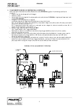
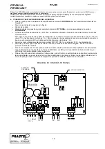
The amplifier has: 

• 

An SW1 two contact Dip-Switch for enabling the individual beams (lever position ON), 

• 

Two red LEDs indicating the beam state  
LED on = beam interrupted or disabled / LED off = beam aligned and uninterrupted 

• 

A TR1 potentiometer for adjusting beam attenuation  
cursor completely to the right = minimum capacity / cursor completely to the left = maximum capacity 
The table below shows the maximum capacity of a CR9MS probe in function of TR1 Trimmer cursor position. 


TR1 Trimmer Cursor Position 

Capacity CR/9MS [mt] 

Anticlockwise end of stroke 

7/8 7.5 
6/8 6 
5/8 5 
4/8 4 
3/8 3 
2/8 2.5 
1/8 2 
Clockwise end of stroke 

1.5 


• 

An output activated when one of the beams is interrupted. 

• 

A green LED indicating the state of the output (LED on = Exit not active, LED off = exit active) 

• 

A TEST button to check correct amplifier functioning. If the beams are aligned (red LEDs off), by pressing the button 
the transmission train of impulses on the individual beams is disabled, so if the amplifier is working correctly the red 
LEDs will remain lit for the whole time the button is held down. 

• 

A Test input on the terminal board. If the FOTO9S2A receives, on the TEST input, an impulse of a minimum 

duration of 70msec it signals correct functioning by activating the output. 


2. MAIN 

FEATURES 

• 

Multiplex synchronised system for high immunity to disturbance 

• 

Redundant electronics 

• 

Management of 2 beams 

• 

1 relay output in N.O. / N.C. exchange  corresponding to interruption of one of the two beams with an intervention 
time of 50msec 

• 

Easy installation and alignment of the probes, thanks to the “Intensity Attenuation” of infrared rays function by means 
of a trimmer. 

• 

Can be coupled with the Prastel probe models: CR9MS, CR9MS9, CR9MSD, CR9MSP, CRFC, CR20MS. 

• 

Conformity with reference European Directives: Electromagnetic Compatibility (EMC) 89/336/CEE 


3. TECHNICAL 

CHARACTERISTICS 


Supply  

12

÷

24 Vac/dc  

±

 10% 

Power absorbed 
Current absorbed  

Max. 1 W  a 12Vac Max.1.5W a 24Vac 
Max 60mA (2 beams enabled) 

I.R wavelength. 

850 nm 

Range 

0,1 ÷ 20 m nominal (depending on probes used). 

Relay outputs (contact clean in exchange) 

N.A. / N.C. 

Relay intervention time 

50 ms  

Reset time 

0,5 s 

Working temperature  

-20 

°

÷

 +55 

°

Size 

110 X 75 X 35 mm FOTO9S2A, 110 X 55 X 75 mm FOTO9S2AST 

Weight 

400 g FOTO9S2A, 500 g FOTO9S2AST 

 
The FOTO9S2A device must be installed inside another casing that features an IP rating of at least X4. The inside of the casing must be accessible 
by means of appropriate tools.  
 
The photocell is an auxiliary device for the detection of persons and/or objects and must therefore be used in conjunction with a security device.  
 
The photocell must be subjected to periodical checks at least once every 6 months.


                       FOTO9S2A 

Содержание FOTO9S2A

Страница 1: ...ulsante si disabilita la trasmissione del treno di impulsi sui singoli raggi pertanto se l amplificatore funziona correttamente avverrà l accensione dei led rossi per tutto il tempo per cui il pulsante è tenuto premuto Un ingresso di Test in morsettiera Se il FOTO9S2A riceve sull ingresso di TEST un impulso della durata minima di 70msec segnala il suo corretto funzionamento attivando l uscita 2 CA...

Страница 2: ...o comune RX e il cavetto centrale filo bianco sui morsetti 1 o 2 Abilitare i raggi utilizzati mediante il Dip Switch SW1 ON raggio abilitato OFF raggio disabilitato Alimentare e verificare che il LED Rosso associato ad ogni raggio abilitato sia spento Se ciò non accade provvedere ad allineare le sonde Premere il pulsante di Test per la verifica del corretto funzionamento dell amplificatore In ques...

Страница 3: ...n train of impulses on the individual beams is disabled so if the amplifier is working correctly the red LEDs will remain lit for the whole time the button is held down A Test input on the terminal board If the FOTO9S2A receives on the TEST input an impulse of a minimum duration of 70msec it signals correct functioning by activating the output 2 MAIN FEATURES Multiplex synchronised system for high...

Страница 4: ...t the braided wire to the common terminal RX and the central cable white wire to terminals 1 or 2 Enable the beams utilised by means of the Dip Switch SW1 ON beam enabled OFF beam disabled Power up and check that the Red LED associated with each enabled beam is off If this is not the case align the probes Press the Test button to verify correct functioning of the amplifier In this way impulse tran...

Страница 5: ... en appuyant sur le bouton on désactive la transmission du train d impulsions sur chaque rayon donc si l amplificateur marche bien les leds rouges restent allumées tant que l appui sur le bouton est maintenu Une entrée de Test sur le bornier Si l amplificateur FOTO9S2A reçoit sur l entrée de TEST une impulsion d une durée d au moins 70 millisecondes il signale son bon fonctionnement en activant la...

Страница 6: ...cessaire de relier la tresse sur la borne commun RX et le câble central fil blanc sur les bornes 1 ou 2 Activer les rayons utilisés au moyen du commutateur DIP SW1 ON rayon activé OFF rayon désactivé Alimenter et vérifier si la led rouge associée à chaque rayon activé est éteinte Si ce n est pas le cas aligner les sondes Appuyer sur le bouton de Test pour vérifier le bon fonctionnement de l amplif...

Страница 7: ...eiden Strahlen unterbrochen wird Eine grüne Led für die Anzeige des Status des Ausgangs Led leuchtet Ausgang nicht aktiviert Led aus Ausgang aktiv Ein TEST Taster für die Überprüfung des einwandfreien Betriebs des Verstärkers Wenn die Strahlen zentriert sind rote Leds aus dann wird beim Drücken der Taste die Übertragung der Impulsfolge deaktiviert das heißt wenn der Verstärker korrekt funktioniert...

Страница 8: ...eiter rot an der gemeinsamen Klemme TX und die Umklöppelungen an den Klemmen 1 oder 2 anschließen Für den Anschluss der Empfänger Sonden müssen Sie hingegen die Umklöppelung am gemeinsamen Leiter RX und den mittleren Leiter weiß an den Klemmen 1 oder 2 anschließen Schalten Sie die Strahlen frei mit Hilfe des Dip Switch SW1 ON Strahl freigeschaltet OFF Strahl deaktiviert Speisen Sie und stellen Sie...

Страница 9: ...apagado Salida activa Un pulsador de PRUEBA para verificar el correcto funcionamiento del amplificador Si los rayos están alineados leds rojos apagados al presionar el pulsador se desactiva la transmisión del tren de impulsos en cada rayo Por lo tanto si el amplificador funciona correctamente se producirá el encendido de los leds rojos durante todo el tiempo que el pulsador se mantenga presionado ...

Страница 10: ...smisión es necesario conectar el cable central hilo rojo en el borne común TX y las trenzas en los bornes 1 ó 2 Para la conexión de las sondas de recepción es necesario conectar la trenza en el borne común RX y el cable central hilo blanco en los bornes 1 ó 2 Activar los rayos utilizados mediante el conmutador DIP SW1 ON rayo activado OFF rayo desactivado Alimentar y verificar que el LED rojo asoc...

Страница 11: ...re installed that compromise the integrity safety and operation of the product Only original spares must be used for repair or replacement of parts The installer must supply all information regarding the operation maintenance and use of individual components and of the system as a whole MAINTENANCE To guarantee the efficiency of the product it is essential that qualified professionals perform main...

Страница 12: ... que estar ratificadas por documentos Estos documentos deben ser conservados por el usuario y estar siempre a disposición del personal competente encargado ADVERTENCIAS PARA EL USUARIO Leer atentamente las instrucciones y la documentación adjunta El producto tiene que ser destinado al uso para el que ha sido concebido Otro uso será considerado impropio y por tanto peligroso Además las informacione...

Отзывы: