Pragati BTP-100 Скачать руководство пользователя страница 5

6

                                                                          BI-DIRECTIONAL TOOL TURRETS

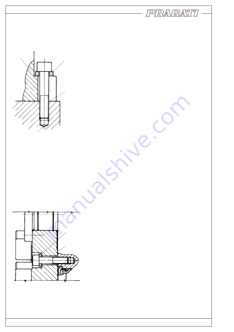
2. Fitment on the machine :

Seating surface of the machine should be flat to ensure proper
contact with the turret base. Machine surface should be either
scraped or surface-ground.

Turret should be aligned by dialing surface of the indexing
flange. Clamping bolts should be tightened after aligning the
seating surface, square to the lathe axis.
Clamping bolts should use machine washers of extra thickness
(min.5 mm) to ensure proper clamping.
Dowel Pins are not recommended for ensuring the alignment
of turret. It is preferable to allow the turret to slip in the event
of an accidental shock or overload. This slipping absorbs
some of the energy of the shock and reduces the possible
damage. Turret can again be brought back to alignment by
dialing a reference surface on the tool disc.

There is one more reason for avoiding the dowel pin.  Acci-
dental collisions are not un-common in the field of CNC lathes.
In the event of a collision, dowel pins can get sheared or
damaged. It is a difficult task to remove such dowel pins, and
to fit new ones. New dowels may involve enlarging the
damaged hole by drilling and reaming. This is difficult to do at

the customer's place. This is a difficult operation to be done on site, and is most likely to be less than perfect.
On the other hand, it is perfectly possible to use the turret and tool disc without the use of dowels. The friction
joint can easily take up normal cutting loads, including occasional over loads.
Pragati turrets, therefore, do not have a provision of dowelling the body to the base.

TOOL
DISK

3. Fitment of Tool Disc on Turret Flange :

Tool disc is to be fitted on the indexing flange with the help of
clamping bolts, and machine washers. Disc should be angularly
adjusted within the clearance of the bolt holes, to get the correct
centre height of the tool. It should then be firmly clamped by
tightening the bolts. Dowel pins for ensuring the position are not
recommended for the reasons explained earlier.

However, dowel pin can be used for the purpose of alignment, but
it is recommended to remove the pin after clamping the tool disc
in position. There is a provision of soft areas on the indexing flange
to facilitate drilling and reaming for dowel pins.

Bolt holes in the tool disc should be of extra large size to allow for
angular adjustment. Extra thick machine washers should be used
to ensure proper clamping.

TURRET
BODY

FLAT
SEATING
SURFACE
(SCRAPED OR
GROUND)

EXTRA THICK
WASHERS

OVERSIZE
BOLT HOLE

EXTRA
THICK
WASHERS

FIG 3.1

FIG 2.1

Содержание BTP-100

Страница 1: ...BI DIRECTIONAL TOOL TURRETS TOOL TURRETS TOOL TURRETS TOOL TURRETS TOOL TURRETS INSTRUCTION MANUAL JUNE 2003 BTP 63 BTP 80 BTP 100 BTP 125 v v v v v v v v v v v v v v v v v v v v...

Страница 2: ...0 8 Handcranking 11 9 Lubrication 11 10 Turret control flow chart 12 11 Requirements of turret control 13 12 Adjustment of rotary encoder 14 13 Adjustment of proximity switch 15 14 Replacement of the...

Страница 3: ...gforceandpullsthesliding coupling out of engagement Further 180 approx movement of cam shaft indexes the follower shaft through 90 which in turn indexes the turret by 30 or 45 depending on gear ratio...

Страница 4: ...during one revolution of the cam shaft CAM ANGLE MOTOR TURRET CLAMP SWITCH BIT 1 BIT 2 BIT 4 BIT 8 STROBE PARITY ENCODER POSITION OF COUPLING TEETH DRUM CAM PROFILE PARRALLEL INDEX DRIVE 1 0 1 0 1 0...

Страница 5: ...at the customer s place This is a difficult operation to be done on site and is most likely to be less than perfect On the other hand it is perfectly possible to use the turret and tool disc without...

Страница 6: ...ssages in the tool disc before reaching the tool point It might therefore be necessary to employ high pressure coolant pump to ensure sufficient flow at tool point Coolant passages in tool turret can...

Страница 7: ...ical Connections 8 BI DIRECTIONAL TOOL TURRET 1 4 2 3 1 Torque Motor 2 Proximity Switch 3 Absolute Encoder 4 Thermal Relay BTP 100 1 9 KVA BTP 80 1 6 KVA BTP 63 1 2 KVA BTP 125 2 3 KVA PROXIMITYSWITCH...

Страница 8: ...s conduits They also give excellent protection against damage by hot chips FIG 6 2 DETAILS OF ELECTRICAL TERMINALS MOTORCURRENT Amps USEFUSERATINGABOUT THREETIMESMOTOR CURRENT MINIMUM 6A FUSE TO BE US...

Страница 9: ...lid state relays should be incorporated in the motor circuit to ensure fastest possible dis connection Regular contactors can be used for motor direction selection followed by solid state relays at le...

Страница 10: ...pproachable 3 Use a suitable cranked spanner to crank the motor 4 After cranking do not forget to place cover 119 back in position 119 118 114 HEX END FIG 8 1 FIG 9 1 9 Lubrication Turret is lubricate...

Страница 11: ...AND START POSITION X DEMAND POSITION Y N NUMBER OF INDEX POSITIONS 8 12 OR 24 DEMAND VALID 1 Y N NO YES X Y Y X N 2 X Y N 2 START TORQUE MOTOR CCW START TORQUE MOTOR CW TURRET CLAMP SWITCH OFF E D B N...

Страница 12: ...layshouldtripthemotorcontactor andalsogive Motoroverheating signaltothecontrol circuit Motor contactor should be tripped without depending on PLC software Typical circuit diagram is given in page 9 11...

Страница 13: ...It is then possible that valid encoder feedback is not available because the turret has stopped in an intermediate position In such acase inMDImode thecontrolshouldchooseafixeddirectionofmotorrotatio...

Страница 14: ...ch Bring the turret in clamped position by hand cranking Proximity switch is approachable after removing back cover 60 Switch is held in a clamp 153 and the clamp is bolted to the turret body by socke...

Страница 15: ...FIG 15 2 VIEW WITH BACK COVER AND MOTOR REMOVED ACTUAL ORIENTATION OF AXES IS VISIBLE IN THIS VIEW 15 Assembly Drawings FIG 15 1 OVERALL ASSEMBLY ALL AXES ARE SHOWN IN ONE PLANE FOR CLARITY 140 141 14...

Страница 16: ...FIG 15 3 MAIN SPINDLE ASSEMBLY BI DIRECTIONAL TOOL TURRETS 17...

Страница 17: ...18 BI DIRECTIONAL TOOL TURRETS FIG 15 4B INDEXING DRIVE BTP 125 BTP 100 FIG 15 4A INDEXING DRIVE BTP 80 BTP 63...

Страница 18: ...BI DIRECTIONAL TOOL TURRETS 19 FIG 15 6 MOTOR ASSEMBLY FIG 15 5 COOLANT VALVE ASSEMBLY...

Страница 19: ...D SCR 112 STATOR 113 ROTOR 114 PINIONSHAFT 115 BEARING 116 CIRCLIP 117 THREADED 118 SOC HD SCR 119 COVER 120 O RING 121 MOTORBODY 130 COOLANTVALVEBUTTON 131 O RING 132 SPRING 133 O RING 134 PLUG 135 G...

Страница 20: ...emoving circlip 88 fig 15 4 Loosen clamping screws 15 of friction ring coupling and pull out the index gear 13 Shafts II III IV can now be pulled out If necessary use threaded holes at the shaft centr...

Страница 21: ...ge and fixed coupling compo nents 31 34 27 3 33 and keep thisassemblyinverticalpositionon a table fig 17 3 It is convenient if the assembly could be clamped to the table with the help of a plate as sh...

Страница 22: ...lange 25 by a newflangeofsuitableextrathickness 17 17 Remove disc springs 11 and screwinlocknut 12 tillitbuttsagainst shaft shoulder Measure the gap be tween the nut face and threaded shoulder fig 17...

Страница 23: ...eAssemblyofSpin dle and indexing drive Axis I II and III in main Body fig 17 7 Fitthepartialspindleassemblyintothe mainbody 45 withthehelpofbolts 2 and cyl pins 40 Also ensure that O Ring 41 is in pla...

Страница 24: ...s located in back plate Clamp back plate to body with the help of bolts 150 and cylindrical pins 151 Now tighten bolts 15 to clamp indexing gear 13 onto the spindle Boltsareapproachablethroughholes in...

Страница 25: ...Procedure for adjustment of ringfeder clamps 60 Back Cover 160 Drain Plug 24 Coolant Ring 26 coolant flange 162 Encoder connector strip 26 BI DIRECTIONAL TOOL TURRETS 18 Adjustment of Ringfeder Clamp...

Страница 26: ...indexing flange and tool disc at some other tool position In such a case tool position number and encoder feedback will not match Crank the motor and bring the turret in clamped position as indicated...

Страница 27: ...ller 78 Indexing drive 8 15 4 18 6 Track roller pins 77 Indexing drive 8 15 4 18 GROUP B SPARES 1 Oil seal 58 Spindle assembly 1 15 3 19 2 Oil seal 107 Motor 1 15 6 21 3 O Ring 5 Anti rotation key 1 1...

Страница 28: ...Motor 13 Quantity Id X Wire dia Part No Assembly Reference No 1 110 X 2 0 41 Spindle Assembly 1 1 115 X 2 0 41 Spindle Assembly 2 1 62 X 2 0 34 Spindle Assembly 3 1 129 X 2 0 39 Coolant Ring 4 1 12 X...

Страница 29: ...2 0 133 Coolant valve 9 1 24 X 2 0 5 Anti Rotation key 10 1 135 X 3 0 108 Motor 11 1 25 X 2 0 120 Motor 12 1 60 X 80 X 10 58 Spindle Assembly 13 1 30 X 47 X 7 107 Motor 14 Quantity Id X Wire dia Part...

Страница 30: ...TCH FAULT IN CONTROL CIRCUIT A B C CRANK THE TURRET BY HAND OBSERVE ENCODER SIGNALS IF DEFECTIVE REPLACE ENCODER CHECK WHETHER PROXIMITY SWITCH SIGNAL IS PRESENT AT PROPER TIME DURING HAND CRACKING IF...

Страница 31: ...ragati Automation Pvt Ltd 413 IV Phase 11th Cross Peenya Industrial Area Bangalore 560 058 INDIA Ph 91 80 2836 1543 Fax 91 80 2836 1549 URL http www pragati automation com Years 1 9 7 7 2 0 0 2 S I L...

Отзывы: