


11.3 Manual mode of turret control
Control panel should have a facility to change over the turret control to manual mode. Following facilities
should be available in this mode :
11.31. ’Inching’ the motor in either direction : During servicing, it is sometimes necessary to rotate the motor
for checking the functioning of the turret mechanism. Push button switches should be provided to allow
‘inching’ of the motor in either direction.
11.32. Tool indexing cycle on manual demand : Control system should provide a facility to index the turret
into desired position by manual data entry of ‘tool demand’. This can be either by a ‘thumb wheel’ switch,
or by push button data entry through CNC panel.
Indexing cycle through manual tool demand will be identical to the normal indexing cycle, except for the fact
the cycle will start even if initial signal conditions are not satisfied.
Turret can stop in an unclamped position, if the power fails during the indexing cycle. It is then possible that
valid encoder feedback is not available because the turret has stopped in an intermediate position. In such
a case, in MDI mode, the control should choose a fixed direction of motor rotation (i.e.default direction) and
then index the turret to demanded position.
14
BI-DIRECTIONAL TOOL TURRETS
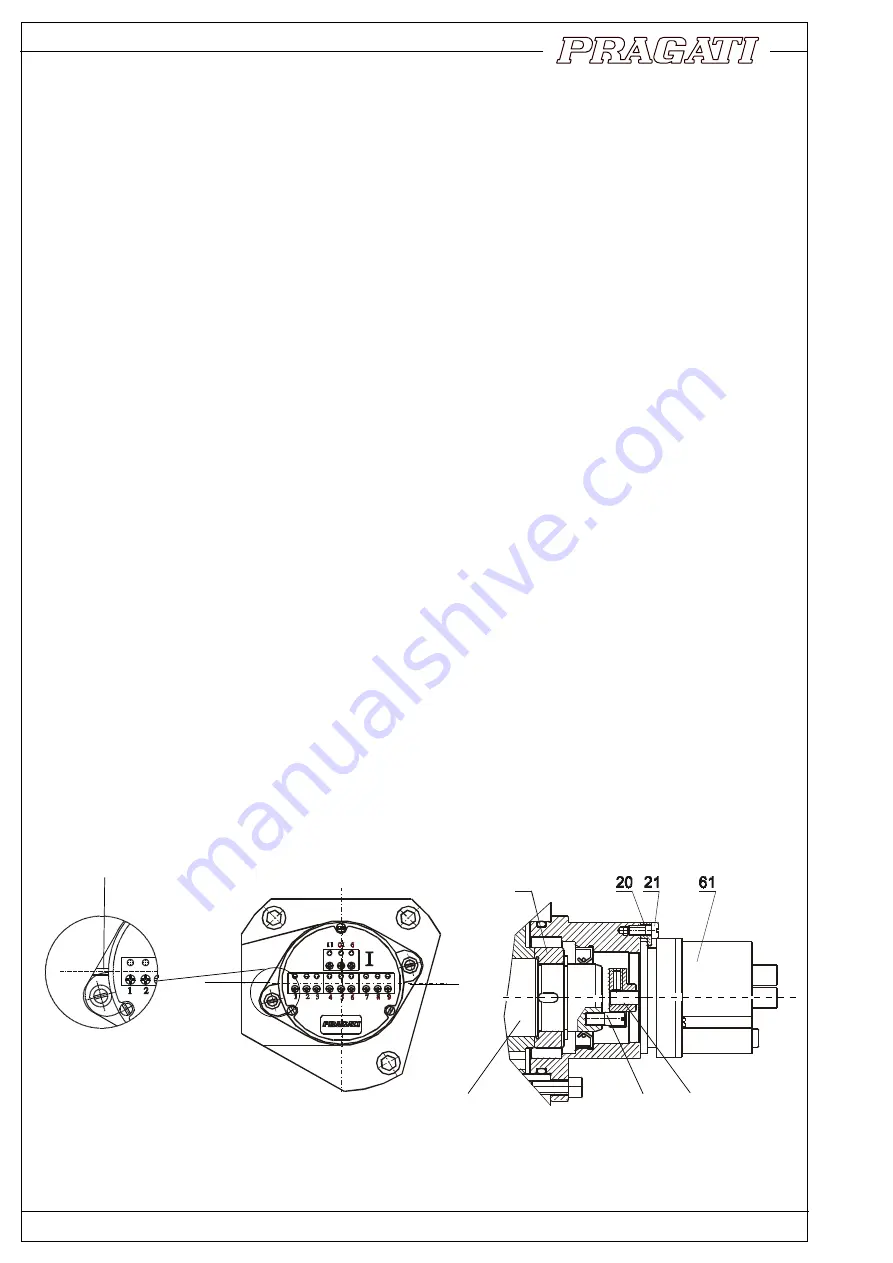
12. Replacement or adjustment of rotary encoder
Rotary encoder is fitted on flange (19) with the help of clamps (20). Encoder can be removed easily by
removing these clamps.
However, care should be taken while mounting the encoder back in its position. Angular position of the
encoder is important. Procedure for setting the encoder in proper angular orientation is as follows :
* Index the turret to any working position by hand cranking the motor shaft. Proper clamped position is
indicated by lighted LED on proximity switch (152).
* Align the slot of the drive dog(23) with pin(22) on main spindle(31) and mount the encoder on the flange(19).
* Now rotate the encoder such that marks on encoder matches the marks on flange.
* Clamp the encoder in this position by tightening clamps (20).
FIG 12.1
A,B REFERENCE SLOTS
A
B
31
22
23
SLOT ON THE MOUNTING
BLOCK (A)
19
Содержание BTP-100
Страница 16: ...FIG 15 3 MAIN SPINDLE ASSEMBLY BI DIRECTIONAL TOOL TURRETS 17...
Страница 17: ...18 BI DIRECTIONAL TOOL TURRETS FIG 15 4B INDEXING DRIVE BTP 125 BTP 100 FIG 15 4A INDEXING DRIVE BTP 80 BTP 63...
Страница 18: ...BI DIRECTIONAL TOOL TURRETS 19 FIG 15 6 MOTOR ASSEMBLY FIG 15 5 COOLANT VALVE ASSEMBLY...


