background image


Version No. V3R0

 5


9116 Universal converter 

safety Manual

the end user must ensure that the applied sensor wiring does not introduce 
failures exceeding the requirements for the safety application.

4.3.2  Sensor errors

If the loop supply is used to supply a current input signal, the sensor error 
indication shall be enabled on the safety output(s).
If sensor error detection is disabled, or if any of the conficurations below 
are used, the user must ensure that the applied sensor, including wiring, 
has a failure rate that qualifies it for the safety application without sensor 
error detection enabled:

  Input is current, 0-20 mA

  Input is voltage

  Input is linear resistance and R_0% < 18 

W

 (no short circuit detection)

  Input it Pt10, Pt20 or Pt50 (no short circuit detection)

  Input is potentiometer (no short circuit detection on arm)

4.3.3  Process calibration

If a process calibration is taken into SIL-mode operation, it is mandatory 
that the accuracy of the device (and sensor, if applicable) are tested by the 
end user after SIL-mode is entered, in addition to the normal functional 
test. Refer to section 14 - Safe parameterisation - user responsibility.

4.3.4  analogue output

The connected safety PLC shall be able to detect and handle the fault 
indications on the analogue output of the 9116 converter by having a 
NAMUR NE43-compliant current input.

4.3.5  Relay output

The relay output shall only be connected to equiment which has a current 
limiting function of 2 A.
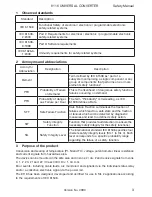
4.4 

failure rates

The basic failure rates from the Siemens standard SN 29500 are used as the failure 
rate database.
Failure rates are constant, wear-out mechanisms are not included.
External power supply failure rates are not included.

4.5 

Safe parameterisation

The user is responsible for verifying the correctness of the configuration 
parameters. (See section 14 Safe parameterisation - user responsibility).
Manual override may not be used for safety applications.

4.6 

Installation in hazardous areas

The IECEx Installation drawing, ATEX Installation drawing and FM Installation 
drawing shall be followed if the products are installed in hazardous areas.

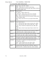
5  functional specification of the safety function

Conversion of current signals (0...20 mA or 4...20 mA), voltage signals, potentiometer, linear 
resistance, RTD sensor signals or thermocouple sensor signals from hazardous areas to a 
4...20 mA current output signal, and/or an output relay, within specified accuracy.

Содержание 9116 Series

Страница 1: ...9 1 1 6 U n i v e r s a l c o n v e r t e r N o 9 1 1 6 V 1 0 4 U K P r o d u c t v e r s i o n 9 1 1 6 0 0 3 ...

Страница 2: ...electronics A S offre une large gamme de produits pour le traite ment des signaux analogiques et numériques dans tous les domaines industriels La gamme de produits s étend des transmetteurs de température aux afficheurs des isolateurs aux interfaces SI jusqu aux modules universels Vous pouvez compter sur nos produits même dans les conditions d utilisation sévères p ex bruit électrique vibrations e...

Страница 3: ...heck 12 Input signal outside range 13 Sensor error detection 13 Hardware error 14 Connections 16 Block diagram 17 Signal error and cable fault indications without display front 18 Configuration operating the function keys 19 Routing diagram 24 Routing diagram Advanced settings ADV SET 26 Scrolling help texts in display line 3 27 Graphic depiction of window 29 Graphic depiction of setpoint 30 Appen...

Страница 4: ... voltages have been defined as the ranges 75 1500 Volt DC and 50 1000 Volt AC Technicians are qualified persons educated or trained to mount operate and also troubleshoot technically correct and in accordance with safety regulations Operators being familiar with the contents of this manual adjust and operate the knobs or potentiometers during normal operation Warning The following operations shoul...

Страница 5: ... the correct handling of the device please contact your local distributor or alternatively PR electronics A S www prelectronics com The use of stranded wires is not permitted for mains wiring except when wires are fitted with cable ends Descriptions of input output and supply connections are shown in the block diagram and on the side label The device is provided with field wiring terminals and sha...

Страница 6: ...he device is easily accessible Cleaning When disconnected the device may be cleaned with a cloth moistened with distilled water Liability To the extent the instructions in this manual are not strictly observed the customer cannot advance a demand against PR electronics A S that would otherwise exist according to the concluded sales agreement How to demount system 9000 Picture 1 By lifting the bott...

Страница 7: ...or higher accuracy The device automatically detects whether it must supply an active or a passive current signal Application The device can be mounted in the safe area and in zone 2 cl 1 div 2 and receive signals from zone 0 1 2 and zone 20 21 22 including M1 Class I II III Div 1 Gr A G Conversion and scaling of temperature voltage potentiometer and linear resistance signals Power supply and signa...

Страница 8: ...s Analogue 0 4 20 mA and relay Relay Relay N O Rail 24 VDC Rail Gnd Power rail Status relay signal Output signals Order separately CJC connector 5910Ex Current Volt age Device status Device status Gnd Supply 19 2 31 2 VDC N C Power connection Supply via power rail Zone 0 1 2 20 21 22 M1 Cl I II III div 1 gr A G Zone 2 Cl 1 div 2 gr A D or safe area No connection No connection ...

Страница 9: ...other and download the configuration of the first unit to subsequent units Fixed display for visualisation of process data and status Technical characteristics LCD display with 4 lines Line 1 H 5 57 mm shows input status line 2 H 3 33 mm toggels between input value and tag no Line 3 H 3 33 mm shows output value and UNIT Line 4 shows status for relay and communication and whether the device is SIL ...

Страница 10: ... Programming front 4501 Signal noise ratio Min 60 dB 0 100 kHz Response time 0 90 100 10 Temperature input programmable 1 60 s mA V input programmable 0 4 60 s Calibration temperature 20 28 C Accuracy the greater of the general and basic values General values Input type Absolute accuracy Temperature coefficient All 0 1 of span 0 01 of span C 4501 Display programming front 4511 Modbus communication...

Страница 11: ...front HxWxD 109 x 23 5 x 116 mm Protection degree IP20 Weight 185 g 200 g with 4501 EMC immunity influence 0 5 of span Extended EMC immunity NAMUR NE 21 A criterion burst 1 of span Basic values Input type Basic accuracy Temperature coefficient mA 16 µA 1 6 µA C Volt 20 µV 2 µV C Pt100 Pt200 Pt 1000 0 2 C 0 02 C C Pt500 Ni100 Ni120 Ni 1000 0 3 C 0 03 C C Pt50 Pt400 Ni50 0 4 C 0 04 C C Pt250 Pt300 0...

Страница 12: ...rnal sensor in connector 5910 20 28 C 1 C 20 20 C and 28 70 C 2 C via internal CJC sensor 2 0 C 0 4 C t t internal temperature ambient temperature Sensor error detection Programmable ON or OFF only wire breakage Input type Min value Max value Standard Pt100 Ni100 Linear resist Potentiometer 200 C 60 C 0 Ω 10 Ω 850 C 250 C 10000 Ω 10000 Ω IEC60751 DIN 43760 Type Min value Max value Standard B E J K...

Страница 13: ... mA 600 Ω 12 VDC Load stability 0 01 of span 100 Ω Sensor error reaction 0 3 5 23 mA none NAMUR NE 43 Upscale Downscale 23 mA 3 5 mA Output limitation on 4 20 and 20 4 mA signals 3 8 20 5 mA on 0 20 and 20 0 mA signals 0 20 5 mA Current limit 28 mA 2 wire 4 20 mA output Signal range 4 20 mA Load stability 0 01 of span 100 Ω Load resistance Vsupply 3 5 0 023 A Ω External 2 wire supply range 3 5 26 ...

Страница 14: ...hips Offshore Stand f Certific No 2 4 I S Ex ATEX 94 9 EC KEMA 10ATEX0053 X IECEx IECEx KEM 10 0022X c FM us 3038267 C INMETRO NCC 12 1309 X GOST Ex Functional Safety exida Cert No PREl 070902 P0002 C05 SIL2 Certified Fully Assessed acc to IEC 61508 FMEDA report www prelectronics com of span of the currently selected measurement range Configuration of sensor error check Sensor error check Device C...

Страница 15: ...ge 2 C IN HI temperature range 2 C Sensor error detection SE BR SE SH Input Range Readout Condition CURR Loop break 4 20 mA SE BR 3 6 mA 21 mA POTM All SE BR on all 3 wire SE BR Sensor broken SE SH Sensor shorted LIN R All SE BR Sensor broken or wire resistance too high For Lin R_0 app 18 Ω SE SH Sensor shorted TEMP All SE BR Sensor broken or wire resistance too high Pt100 to Pt1000 and Ni50 to Ni...

Страница 16: ...e or version TY ER Configuration read from EEprom has invalid type or rev no Hardware error RA ER RAM error Hardware error IF ER Internal Flash error Hardware error SW ER SW monitor error Hardware error AD ER A D converter error Hardware error AO SU Analogue output supply error Hardware error CA ER Factory calibration error Hardware error CM ER Main CPU error Hardware error RE ER Relay readback er...

Страница 17: ... help text is shown If the error is a sensor error the display backlight flashes as well this is acknowledged stopped by pushing the OK button Error is acknowledged by resetting the device power Error can be disregarded by selecting input type different than TC Error is acknowledged by stepping through the basic setup ...

Страница 18: ...24 V N C 91 92 93 94 95 NC NC 24 V 1 3 2 CJC 44 Connections Inputs Outputs Supply and status relay Current Active output Relay RTD 3 4 wire RTD 2 wire Resistance 2 wire Resistance 3 4 wire Potentiometer Current Voltage 2 wire transmitter Gnd 2 wire transmitter Passive output Order separately CJC connector 5910Ex Gnd Power Rail connections NC no connection Error signal TC internal CJC sensor TC CJC...

Страница 19: ...H I o20 mA I 800 0 1 Tx 4 3 2 I mA mA Block diagram Device status Green Relay status Yellow Ch status Red Status relay N C Status relay N C Gnd Supply 24 VDC Relay N O Relay N O Gnd Power Rail connections Input RTD conn wires Potentiometer TC Volt age Current mA output Supply Relay output NC no connection ...

Страница 20: ...FF OFF De energized Closed Device failure OFF ON De energized Closed Device OK Flashing Energized Open Signal OK Flashing OFF Energized Open Output relay energized Flashing ON OFF Energized Open Output relay energized w wire short break Flashing ON Flashing De energized Closed if enab led Output relay de energized w wire short break Flashing OFF Flashing De energized Closed if enab led Output rela...

Страница 21: ...aving the changed values or parameters If no key is activated for 1 minute the display will return to the default state 1 0 without saving the changed values or parameters Further explanations Password protection Programming access can be blocked by assigning a password The password is saved in the converter in order to ensure a high degree of protection against unauthorised modifications to the c...

Страница 22: ... the device Steady red LED indicates fatal error Flashing red LED indicates sensor error Relay functions 5 different settings of relay function can be selected Setpoint The unit works as a single trip amplifier Window The relay has a window that is defined by a low and a high set point On both sides of the window the relay has the same status Error function The relay is activated by sensor error P...

Страница 23: ...signal not necessarily 0 is applied and the actual value is entered via 4501 Then a high signal not necessarily 100 is applied and the actual value is entered via 4501 If you accept to use the calibration the device will work according to this new adjustment If you later reject this menu point or choose another type of input signal the device will return to factory calibration Process simulation f...

Страница 24: ...rsions of help texts that will appear in the menu You can choose between UK DE FR IT ES SE and DK Power rail In the menu RAIL you can choose if sensor errors are transmitted to the central surveillance in the PR 9410 power control unit Safety integrity level See Safety Manual for details Red t param config manu ...

Страница 25: ...Txt 12 1111 111 1 11 11 1 111 1 2 3 UNIT Txt 11 C mA rpm 70 units 1 2 3 CURR IN TYPE Txt 3 3 4 20 I RANGE Txt 5 0 20 4 20 1 2 3 LIN R IN TYPE Txt 3 3 3W CONNEC Txt 6 4W 3W 2W 1 2 3 POTM IN TYPE Txt 3 3 0 R 0 Txt 7 0000 9999 1 2 3 0 R 100 Txt 8 0000 9999 1 2 3 1 0 1 2 1 1 3 3W CONNEC Txt 6 4W 3W 2W 1 2 3 3W CONNEC Txt 6 4W 3W 2W 1 2 3 CJC INT CONN 1 2 3 1 2 SE BR o3 50mA INT II30 00 Txt 2 Txt 10 Tx...

Страница 26: ...ther the device is SIL locked Static dot SIL locked and flashing dot not SIL locked 1 1 Only if password protected 1 2 Only if FastSet is activated and the relay function is setpoint 1 3 Only if input types support sensor error check Not valid for these input signals 0 20 mA and voltage 1 4 Only if input signal is temperaure 1 5 Only if the configuration is not protected by a pass word Continued o...

Страница 27: ...t 41 849 200 1 2 3 150 0 OUT HI Txt 42 850 0 199 0 1 2 1 3 1 4 1 4 3 0 0 RESP Txt 39 0 0 60 1 2 N O CONTAC Txt 20 3 N O N C 1 2 50 0 SETP Txt 21 850 200 1 2 3 INCR ACT DIR Txt 22 INCR DECR 1 2 3 1 0 HYST Txt 23 262 5 0 1 1 2 SETP REL FUN Txt 19 SETP WIND ERR POW OFF 1 2 3 O I W CONTAC Txt 27 3 O I W C I W 1 2 50 0 SETP LO Txt 28 849 9 200 1 2 3 60 0 SETP HI Txt 28 850 0 199 9 1 2 3 1 0 HYST Txt 30...

Страница 28: ...Txt 43 3 YES EN SIM Txt 51 3 YES NO 1 2 23 0 Txt 52 3 850 0 200 0 1 2 NO REL SIM Txt 53 3 2 0 RAIL SETUP Txt 43 3 YES RAIL ER Txt 63 3 YES NO 1 2 SIL SETUP Txt 43 3 YES EN SIL Txt 64 YES NO 1 2 NO 3 2008 NEW PAS Txt 55 0000 9999 1 2 3 LOCK CONFIG Txt 66 SIL OK 3 3 3 3 3 OPEN LOCK 1 2 LANG SETUP Txt 43 3 UK LANGUA Txt 59 3 DE DK ES FR IT SE UK 1 2 PASS SETUP Txt 43 3 3 YES EN PASS Txt 54 3 YES NO 1...

Страница 29: ...W function relay is controlled by 2 setpoints Select SETPOINT function relay is controlled by 1 setpoint Select Normally Closed contact Select Normally Open contact Set Relay setpoint Select Action on decreasing signal Select Action on increasing signal Set Relay hysteresis Select No error action undefined status at error Select Open relay contact at error Select Close relay contact at error Selec...

Страница 30: ...t circuit Sensor wire breakage Display underrange Display overrange Input underrange Input overrange Input error check input connections and reset power Output error check connentions and reset power Flash memory error chek configuration Invalid configuration type or version Hardware error CJC sensor error check device temperature CJC error check CJC connector block No communication ...

Страница 31: ...6 Product Version 9116 003 29 Graphic depiction of window Hysteresis Setpoint high ON delay OFF delay Relay On Relay On Closed Open Relay contact N O Time Window ON delay OFF delay Hysteresis Setpoint low ...

Страница 32: ...30 9116 Product Version 9116 003 Graphic depiction of setpoint Relay On OFF delay ON delay Input signal Hysteresis Setpoint increasing Time Closed Open Relay contact N O ...

Страница 33: ...9116 Product Version 9116 003 31 Appendix IECEx Installation drawing ATEX Installation drawing FM Installation drawing INMETRO Installation drawing Safety manual ...

Страница 34: ...e shall be installed IECEx Certificate KEM 10 0022X Marking Standards IEC60079 15 2005 IEC60079 11 2011 IEC60079 0 2011 IEC60079 26 2006 20 Ta 60ºC terminal 11 12 13 14 terminal 31 32 33 34 terminal 91 92 93 94 95 Um 253 V max 400 Hz Hazardous area Zone 0 1 2 20 21 and 22 Non Hazardous area or Zone 2 Status relay terminal 33 34 Non hazardous area installation Voltage max 125 VAC 110 VDC Power max ...

Страница 35: ...Ω Module 9116B2 Terminal 51 54 52 54 Group Module 9116B2 Terminal 51 53 Co Group Lo Lo Ro Co Lo Lo Ro Lo Ro Lo Module 9116B1 Terminal 41 42 43 44 Module 9116B1 Terminal 51 52 Group Group Module 9116B2 Terminal 41 42 43 44 Group Lo Ro Lo Ro Module 9116B2 Terminal 51 52 Group Group Co Lo Lo Ro Co Co Lo Lo Ro Co Lo Module 9116B1 Module 9116B2 Module 9116B1 Terminal 51 54 52 54 Group Module 9116B1 Ter...

Страница 36: ...ea Zone 0 1 2 20 21 22 or Zone 2 T 54 53 52 51 44 43 42 41 9116 34 33 32 31 14 13 12 11 Power Rail 4501 54 53 52 51 44 43 42 41 9116 34 33 32 31 14 13 12 11 Power Rail 4501 4 20 mA Loop powered transmitter terminal 11 12 13 14 terminal 31 32 33 34 terminal 91 92 93 94 95 Um 253 V max 400 Hz 20 Ta 60ºC Status relay terminal 33 34 Non hazardous area installation Voltage max 125 VAC 110 VDC Power max...

Страница 37: ...3 32 31 14 13 12 11 Power Rail 4501 54 53 52 51 44 43 42 41 9116 34 33 32 31 14 13 12 11 Power Rail 4501 terminal 11 12 13 14 terminal 31 32 33 34 terminal 91 92 93 94 95 Um 253 V max 400 Hz 20 Ta 60ºC 0 4 20 mA Current source Status relay terminal 33 34 Non hazardous area installation Voltage max 125 VAC 110 VDC Power max 62 5 VA 32 W Current max 0 5 A AC 0 3 ADC Zone 2 installation Voltage max 3...

Страница 38: ...talled ATEX Certificate KEMA 10 ATEX 0053 X Marking Standards EN 60079 0 2009 EN 60079 11 2012 EN 60079 15 2005 EN 60079 26 2007 Hazardous area Non Hazardous area Zone 0 1 2 20 21 22 or Zone 2 terminal 11 12 13 14 terminal 31 32 33 34 terminal 91 92 93 94 95 Um 253 V max 400 Hz Relay output terminal 13 14 Non hazardous area installation Voltage max 250 VAC 30 VDC Power max 500 VA 60 W Current max ...

Страница 39: ... Ω Module 9116B2 Terminal 51 54 52 54 Group Module 9116B2 Terminal 51 53 Co Group Lo Lo Ro Co Lo Lo Ro Lo Ro Lo Module 9116B1 Terminal 41 42 43 44 Module 9116B1 Terminal 51 52 Group Group Module 9116B2 Terminal 41 42 43 44 Group Lo Ro Lo Ro Module 9116B2 Terminal 51 52 Group Group Co Lo Lo Ro Co Co Lo Lo Ro Co Lo Module 9116B1 Module 9116B2 Module 9116B1 Terminal 51 54 52 54 Group Module 9116B1 Te...

Страница 40: ...a Zone 0 1 2 20 21 22 or Zone 2 20 ºC Ta 60ºC T 54 53 52 51 44 43 42 41 9116 34 33 32 31 14 13 12 11 Power Rail 4501 54 53 52 51 44 43 42 41 9116 34 33 32 31 14 13 12 11 Power Rail 4501 4 20 mA Loop powered transmitter terminal 11 12 13 14 terminal 31 32 33 34 terminal 91 92 93 94 95 Um 253 V max 400 Hz Status relay terminal 33 34 Non hazardous area installation Voltage max 125 VAC 110 VDC Power m...

Страница 41: ...31 14 13 12 11 Power Rail 4501 54 53 52 51 44 43 42 41 9116 34 33 32 31 14 13 12 11 Power Rail 4501 terminal 11 12 13 14 terminal 31 32 33 34 terminal 91 92 93 94 95 Um 253 V max 400 Hz 20 ºC Ta 60ºC 0 4 20 mA Current source Relay output terminal 13 14 Non hazardous area installation Voltage max 250 VAC 30 VDC Power max 500 VA 60 W Current max 2 A AC 2 ADC Zone 2 installation Voltage max 32 VAC 30...

Страница 42: ...III Division 1 Group A B C D E F G or Class I Zone 0 1 Group IIC AEx ia IIC or Class I Zone 0 1 Group IIC Ex ia IIC 20 Ta 60ºC Unclassified Location or Hazardous Classified Location Class I Division 2 Group A B C D T4 or Class I Zone 2 Group IIC T4 Simple Apparatus or Intrinsic safe apparatus with entity parameters Vmax Ui Vt Uo Imax Ii It Io Pi Pt Po Ca Ccable Ci La Lcable Li terminal 11 12 13 14...

Страница 43: ...Lo Lo Ro Module 9116B2 Terminal 51 52 Group Co Lo Lo Ro Module 9116B1 Terminal 51 53 Group Co Lo Lo Ro Module 9116B2 Terminal 51 53 Group Module 9116B1 Module 9116B2 Module 9116B1 Terminal 51 54 52 54 Group Co Lo Lo Ro Module 9116B2 Terminal 51 54 52 54 Group Lo Lo Ro Module 9116B2 Terminal 41 42 43 44 Co Lo Lo Ro Installation notes The installation and wiring shall be in accordance with the Canad...

Страница 44: ... 32 31 14 13 12 11 Power Rail 4501 Unclassified Location or Hazardous Classified Location Class I Division 2 Group A B C D T4 or Class I Zone 2 Group IIC T4 Hazardous Classified Location Class I II III Division 1 Group A B C D E F G or Class I Zone 0 1 Group IIC AEx ia IIC or Class I Zone 0 1 Group IIC Ex ia IIC 4 20 mA Loop powered transmitter terminal 11 12 13 14 terminal 31 32 33 34 terminal 91...

Страница 45: ...92 93 94 95 Um 253 V max 400 Hz Hazardous Classified Location Class I II III Division 1 Group A B C D E F G or Class I Zone 0 1 Group IIC AEx ia IIC or Class I Zone 0 1 Group IIC Ex ia IIC Unclassified Location or Hazardous Classified Location Class I Division 2 Group A B C D T4 or Class I Zone 2 Group IIC T4 0 4 20 mA Current Source 20 ºC Ta 60ºC Status relay terminal 33 34 Unclassified location ...

Страница 46: ...e poeira e umidade devem ser instalados INMETRO Certificado NCC 12 1309X Marcas Normas IEC60079 15 2005 IEC60079 11 2011 IEC60079 0 2011 IEC60079 26 2006 20 Ta 60ºC terminais 11 12 13 14 terminais 31 32 33 34 terminais 91 92 93 94 95 Um 253 V máx 400 Hz Área de Risco Zona 0 1 2 20 21 e 22 Área de não Risco ou Zona 2 Relê de estado terminais 33 34 Instalação em área de não Risco Voltagem máx 125 VA...

Страница 47: ...o Group Lo Lo Ro Co Lo Lo Ro Lo Ro Lo Module 9116B1 Terminal 41 42 43 44 Module 9116B1 Terminal 51 52 Group Group Module 9116B2 Terminal 41 42 43 44 Group Lo Ro Lo Ro Module 9116B2 Terminal 51 52 Group Group Co Lo Lo Ro Co Co Lo Lo Ro Co Lo Module 9116B1 Module 9116B2 Module 9116B1 Terminal 51 54 52 54 Group Module 9116B1 Terminal 51 53 Co Lo Lo Ro Co Lo Notas de instalação Instalação em grau de p...

Страница 48: ...ne 2 T 54 53 52 51 44 43 42 41 9116 34 33 32 31 14 13 12 11 4501 54 53 52 51 44 43 42 41 9116 34 33 32 31 14 13 12 11 4501 TRILHO DE ENERGIA TRILHO DE ENERGIA 4 20 mA Transmissor com malha alimentada terminais 11 12 13 14 terminais 31 32 33 34 terminais 91 92 93 94 95 Um 253 V máx 400 Hz 20 Ta 60ºC Rele de estado terminais 33 34 Instalação em área de não Risco Voltagem máx 125 VAC 110 VDC Potência...

Страница 49: ...53 52 51 44 43 42 41 9116 34 33 32 31 14 13 12 11 4501 TRILHO DE ENERGIA TRILHO DE ENERGIA terminais 11 12 13 14 terminais 31 32 33 34 terminais 91 92 93 94 95 Um 253 V máx 400 Hz 20 Ta 60ºC 0 4 20 mA Fonte de Corrente Rele de estado terminais 33 34 Instalação em área de não Risco Voltagem máx 125 VAC 110 VDC Potência máx 62 5 VA 32 W Corrente máx 0 5 A AC 0 3 ADC Instalação em Zona 2 Voltagem máx...

Страница 50: ...Version No V3R0 Safety manual UNIVERSAL CONVERTER 9116 This safety manual is valid for the following product versions 9116 003 9116 002 9116 001 ...

Страница 51: ...roof test procedure 9 11 Procedures to repair or replace the product 9 12 Maintenance 9 13 Documentation for routing diagram 9 13 1 In general 9 13 2 Further explanations 9 13 2 1 Password protection 9 13 2 2 Sensor cable fault information via display front 4501 10 13 3 Advanced functions ADV SET 10 13 3 1 Memory MEM 10 13 3 2 Display setup DISP 10 13 3 3 Password PASS 10 13 3 4 Language LANG 10 1...

Страница 52: ... No V3R0 Safety Manual 9116 Universal converter 15 Fault reaction and restart condition 20 16 User interface 21 16 2 Routing diagram 23 16 3 Routing diagram Advanced settings ADV SET 26 17 Connections diagram 27 ...

Страница 53: ...emand This is the likelihood of dangerous safety function failures occurring on demand PFH Probability of danger ous Failure per Hour The term Probability is misleading as IEC 61508 defines a Rate SFF Safe Failure Fraction Safe Failure Fraction summarises the fraction of failures which lead to a safe state and the fraction of failures which will be detected by diagnostic measures and lead to a def...

Страница 54: ...utput corresponds to the applied input within the safety accuracy Safety accuracy 2 4 2 1 Minimum span For temperature measurements the selected range OUT HI OUT LO and for linear resistance measurements the selected range R 100 R 0 shall be larger or equal to the values below 4 2 2 Range limitations TC type B shall not be used below 400 C 4 3 Associated equipment 4 3 1 RTD or linear resistance se...

Страница 55: ...rameterisation user responsibility 4 3 4 Analogue output The connected safety PLC shall be able to detect and handle the fault indications on the analogue output of the 9116 converter by having a NAMUR NE43 compliant current input 4 3 5 Relay output The relay output shall only be connected to equiment which has a current limiting function of 2 A 4 4 Failure rates The basic failure rates from the S...

Страница 56: ...ut Current output Probability of dangerous Failure per Hour PFH 4 30E 08 Note1 Probability of failure on demand PFD 1 year proof test interval 2 82E 04 Proof test interval 10 of loop PFD 4 years Safe Failure Fraction 93 RTD TC LinR and Potentiometer input Relay output Probability of dangerous Failure per Hour PFH 6 20E 08 Note1 Probability of failure on demand PFD 1 year proof test interval 4 03E ...

Страница 57: ...econds Demand mode High Demand rate 3000 seconds Mean Time To Repair MTTR 24 hours Diagnostic test interval 30 seconds Hardware Fault Tolerance HFT 0 Component Type B SIL capability SIL 2 Description of the Safe State analogue output Output 3 6 mA or Output 21 mA Description of the Safe State relay output Contact open relay de energized Relay lifetime Note2 100 000 times Note1 The 9116 contains no...

Страница 58: ... h for Voltage input Current output Fail Safe Detected 0 000E 0 Fail Safe Undetected 3 95E 07 Fail Dangerous Detected 4 79E 07 Fail Dangerous Undetected 5 60E 08 Failure rates 1 h for Voltage input Relay output Fail Safe Detected 0 000E 0 Fail Safe Undetected 4 80E 07 Fail Dangerous Detected 3 53E 07 Fail Dangerous Undetected 7 60E 08 Failure rates 1 h for Current input Current output Fail Safe De...

Страница 59: ...ease the numerical value or choose the previous parameter 3 will accept the chosen value and proceed to the next menu When configuration is completed the display will return to the default state 1 0 Pressing and holding 3 will return to the previous menu or return to the default state 1 0 without saving the changed values or parameters If no key is activated for 1 minute the display will return to...

Страница 60: ...er with 5 alphanumerics can be entered Functional readout in line 3 of the display can be selected choose between readout of output current or tag no When selecting ALT the readout alternates between output current and tag no 13 3 3 Password PASS Here you can choose a password between 0000 and 9999 in order to protect the device against unauthorised modifications to the configuration The device is...

Страница 61: ...ible in SIL mode 13 3 8 Safety integrity level SIL See section 14 Safe parameterisation user responsibility 14 Safe parameterisation user responsibility 14 1 Safety related configuration parameters 14 1 1 Common parameters Name Function IN TYPE Selected input type TEMP Temperature CURR Current VOLT Voltage LIN R Linear resistance POTM Potentiometer I RANGE Selected fixed input range for current me...

Страница 62: ...Ni120 1000 Ni1000 TC TYPE Thermocouple type for SENSOR TC TC B Thermocuple type B TC E Thermocuple type E TC J Thermocuple type J TC K Thermocuple type K TC L Thermocuple type L TC N Thermocuple type N TC R Thermocuple type R TC S Thermocuple type S TC T Thermocuple type T TC U Thermocuple type U TC W3 Thermocuple type W3 TC W5 Thermocuple type W5 TC Lr Thermocuple type Lr CJC CJC type for SENSOR ...

Страница 63: ... IN TYPE LIN R This value must be R 100 minimum span refer to 4 2 1 R 100 100 input range for linear resistance measurements for IN TYPE LIN R This value must be R 0 minimum span refer to 4 2 1 UNIT Selected temperature unit for IN TYPE TEMP C degrees Celsius F degrees Fahrenheit For IN TYPE TEMP selectable units refer to routing diagram DISP LO 0 display value on 4501 Can be used as base for rela...

Страница 64: ... Closed relay contact for REL FUN SETP N O Normally Open relay contact for REL FUN SETP O I W Relay contact Open Inside Window for REL FUN WIND C I W Relay contact Closed Inside Window for REL FUN WIND SETP Relay setpoint value in REL UNI units for IN TYPE TEMP or in UNIT for IN TYPE TEMP for REL FUN SETP SETP LO Relay setpoint low value in REL UNI units for IN TYPE TEMP or in UNIT for IN TYPE TEM...

Страница 65: ...llowed if the relay is used in a safety application EN SIL YES and IN TYPE CUR and loop supply is used to supply a current input signal Note4 Error detection is enabled if OUT ERR none but relay state at sensor erroris undefined 14 1 3 Parameters related to analouge output Name Function O RANGE Fixed output range for current output 0 20 0 20 mA Value not allowed when EN SIL YES Safety applications...

Страница 66: ... to 60 0 seconds USE CAL Use the applied process calibration values NO The last performed process calibration is not used The channel operates with accuracy as specified YES The last performed process calibration is in operation The required accuracy must be verified by user End user must verify by test that the applied process calibration does not introduce failures exceeding the requirements for...

Страница 67: ...OCK in the display IN TYPE 7 Verify input type and press OK I RANGE 8 Verify fixed input current range and press OK ONLY if IN TYPE CURR CONNEC 9 Verify sensor connection type and press OK ONLY if IN TYPE TEMP and SENSOR Ni or Pt or IN TYPE LIN R UNIT 10 Verify temperature unit and press OK ONLY if IN TYPE TEMP SENSOR 11 Verify temperature sensor type and press OK ONLY if IN TYPE TEMP Pt TYPE 12 V...

Страница 68: ...Verify display decimal point for 4501 and press OK ONLY if IN TYPE TEMP DISP LO 21 Verify display value for 4501 at 0 input and press OK ONLY if IN TYPE TEMP DISP HI 22 Verify display value for 4501 at 100 input and press OK ONLY if IN TYPE TEMP REL UNI 23 Verify relay setpoint units and press OK ONLY if IN TYPE TEMP REL FUN 24 Verify relay function and press OK CONTAC 25 Verify relay contact func...

Страница 69: ...K ONLY if REL FUN SETP or WIND OFF DEL 33 Verify relay OFF delay and press OK ONLY if REL FUN SETP or WIND O RANGE 34 Verify fixed output range for current output OUT ERR 35 Verify fixed output value on detected sensor error and press OK ONLY if IN TYPE VOLT or IN TYPE CURR and I RANGE 0 20 mA OUT LO 36 Verify temperature for 0 output and press OK ONLY if IN TYPE TEMP OUT HI 37 Verify temperature ...

Страница 70: ...lecting EN SIL NO Go through the setup menu and correct the parameter s Repeat step 1 to 36 with correct parameters 14 3 Functional test The user is responsible to make a functional test after verification of the safety parameters The procedure for periodic proof test described in section 10 shall be used In addition if a process calibration is taken into SIL mode operation refer to section 13 3 A...

Страница 71: ...elect POWER function relay indicates power status OK Select ERROR function relay indicates sensor error only Select WINDOW function relay is controlled by 2 setpoints Select SETPOINT function relay is controlled by 1 setpoint Select Normally Closed contact Select Normally Open contact Set Relay setpoint Select Action on decreasing signal Select Action on increasing signal Set Relay hysteresis Sele...

Страница 72: ...mA is not a valid output range for SIL operation is channel using process compensated calibration data Configuration SIL status Open Locked Sensor short circuit Sensor wire breakage Display underrange Display overrange Input underrange Input overrange Input error check input connections and reset power Output error check input connentions and reset power Flash memory error chek configuration Inval...

Страница 73: ... 2 111 1 DEC P Txt 12 1111 111 1 11 11 1 111 1 2 3 UNIT Txt 11 C mA rpm 70 units 1 2 3 CURR IN TYPE Txt 3 3 4 20 I RANGE Txt 5 0 20 4 20 1 2 3 LIN R IN TYPE Txt 3 3 3W CONNEC Txt 6 4W 3W 2W 1 2 3 POTM IN TYPE Txt 3 3 0 R 0 Txt 7 0000 9999 1 2 3 0 R 100 Txt 8 0000 9999 1 2 3 1 0 1 2 1 1 3 3W CONNEC Txt 6 4W 3W 2W 1 2 3 3W CONNEC Txt 6 4W 3W 2W 1 2 3 CJC INT CONN 1 2 3 1 2 SE BR o3 50mA INT II30 00 ...

Страница 74: ...ication and whether the device is SIL locked Static dot SIL locked and flashing dot not SIL locked 1 1 Only if password protected 1 2 Only if FastSet is activated and the relay function is setpoint 1 3 Only if input types support sensor error check Not valid for these input signals 0 20 mA and voltage 1 4 Only if input signal is temperaure 1 5 Only if the configuration is not protected by a pass w...

Страница 75: ...99 0 1 2 1 3 1 4 1 4 3 0 0 RESP Txt 39 0 0 60 1 2 N O CONTAC Txt 20 3 N O N C 1 2 50 0 SETP Txt 21 850 200 1 2 3 INCR ACT DIR Txt 22 INCR DECR 1 2 3 1 0 HYST Txt 23 262 5 0 1 1 2 SETP REL FUN Txt 19 SETP WIND ERR POW OFF 1 2 3 O I W CONTAC Txt 27 3 O I W C I W 1 2 50 0 SETP LO Txt 28 849 9 200 1 2 3 60 0 SETP HI Txt 28 850 0 199 9 1 2 3 1 0 HYST Txt 30 262 5 0 1 1 2 WIND REL FUN Txt 19 3 OPEN ERR ...

Страница 76: ...IM Txt 53 3 2 0 RAIL SETUP Txt 43 3 YES RAIL ER Txt 63 3 YES NO 1 2 SIL SETUP Txt 43 3 YES EN SIL Txt 64 YES NO 1 2 NO 3 2008 NEW PAS Txt 55 0000 9999 1 2 3 LOCK CONFIG Txt 66 SIL OK 3 3 3 3 3 OPEN LOCK 1 2 LANG SETUP Txt 43 3 UK LANGUA Txt 59 3 DE DK ES FR IT SE UK 1 2 PASS SETUP Txt 43 3 3 YES EN PASS Txt 54 3 YES NO 1 2 NO 0000 NEW PAS Txt 55 3 9999 0000 1 2 YES EN FAST Txt 56 YES NO 1 2 3 YES ...

Страница 77: ... No V3R0 27 9116 Universal converter Safety Manual 17 Connections diagram Inputs Outputs Supply and status relay Current Active output Relay RTD 3 4 wire RTD 2 wire Resistance 2 wire Resistance 3 4 wire Potentiometer Current Voltage 2 wire transmitter Gnd 2 wire transmitter Passive output Order separately CJC connector 5910Ex Gnd Power Rail connections NC no connection Error signal TC internal CJC...

Страница 78: ...lvanic isolators for analogue and digital signals as well as HART signals A wide product range with both loop powered and universal isolators featuring linearisation inversion and scaling of output signals Isolation Interfaces for analogue and digital signals as well as HART signals between sensors I P converters frequency signals and control systems in Ex zone 0 1 2 and for some modules in zone 2...

Страница 79: ...prelectronics fr sales prelectronics fr www prelectronics de sales prelectronics de www prelectronics es sales prelectronics es www prelectronics it sales prelectronics it www prelectronics se sales prelectronics se www prelectronics co uk sales prelectronics co uk www prelectronics com sales prelectronics com www prelectronics cn sales prelectronics cn ...

Отзывы: