background image

5114V107-UK

 15

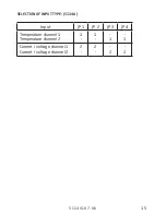
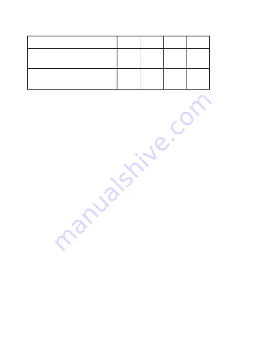
SELECTION OF INPUT TYPE: (5114A)

Input

JP 1

JP 2

JP 3

JP 4

Temperature channel 1 
Temperature channel 2

-

-

1

1

Current / voltage channel 1 
Current / voltage channel 2

-

-

2

2

Содержание 5114

Страница 1: ...5 1 1 4 P r o g r a m m a b l e T r a n s m i t t e r N o 5 1 1 4 V 1 0 7 U K F r o m s e r n o 9 9 0 0 6 1 0 0 1 ...

Страница 2: ...y PR electronics A S offre une large gamme de produits pour le traite mentdessignauxanalogiquesetnumériquesdanstouslesdomaines industriels La gamme de produits s étend des transmetteurs de température aux afficheurs des isolateurs aux interfaces SI jusqu aux modules multifonctions Vous pouvez compter sur nos produits même dans les conditions d utilisation sévères p ex bruit électrique vibrations e...

Страница 3: ...l identification 3 Safety instructions 3 How to demount system 5000 5 Application 6 Technical characteristics 6 Input types 6 Output 7 Configuration 8 Electrical specifications 8 Order 13 5114 connection to Loop Link 13 Block diagram 14 Selection of input type 5114A 15 ...

Страница 4: ...urer the protection provided by the equipment may be impaired WARNING Until the device is fixed do not connect hazardous voltages to the device The following operations should only be carried out on a disconnected device and under ESD safe conditions Dismantlement of the device for setting of DIP switches and jumpers General mounting connection and disconnection of wires Troubleshooting the device...

Страница 5: ...mount operate and also troubleshoot technically correct and in accordance with safety regulations Operators being familiar with the contents of this manual adjust and operate the knobs or potentiometers during normal operation RECEIPT AND UNPACKING Unpack the device without damaging it The packing should always follow the device until this has been permanently mounted Check at the receipt of the d...

Страница 6: ...he device The power switch should be marked with a label telling it will switch off the voltage to the device Year of manufacture can be taken from the first two digits in the serial number CALIBRATION AND ADJUSTMENT During calibration and adjustment the measuring and connection of external voltages must be carried out according to the specifications of this manual The technician must use tools an...

Страница 7: ...t the connectors with hazardous voltages By lifting the bottom lock the device is detached from the DIN rail as shown in picture 1 Then by lifting the upper lock and pulling the front plate simultaneously the PCB is removed as shown in picture 2 Switches and jumpers can now be adjusted By opening the front the programming connector is accessible as shown in picture 3 ...

Страница 8: ...CTERISTICS The unit is based on a microprocessor core with an efficient program operation The basic calibration data and present set up are stored in an EEPROM thereby avoiding the loss or change of data at power off The 2 channel version has a full galvanic isolation between the channels By way of jumpers on the PCB the input in the standard version can be programmed either for a temperature or a...

Страница 9: ...configuration program Loop transmitter supply 17 1 VDC Reference voltage of 2 5 VDC for instance as a supply for potentiometers OUTPUT The analogue standard current voltage output is programmable in the range 0 20 mA for instance 4 20 mA and 0 10 VDC The output voltage can be ordered for a maximum of 12 VDC by a special shunt resistance The output signal is proportional and linear to the value of ...

Страница 10: ...omer specifica tions input type measurement range sensor error detection and output signal ELECTRICAL SPECIFICATIONS Specifications range 20 C to 60 C Common specifications Supply voltage universal 21 6 253 VAC 50 60 Hz 19 2 300 VDC Max required power 1 2 channels 2 1 W 2 8 W Fuse 400 mA SB 250 VAC Isolation voltage test operation 3 75 kVAC 250 VAC PELV SELV IEC 61140 Communications interface Loop...

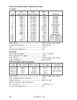
Страница 11: ...D 109 x 23 5 x 130 mm DIN rail type DIN 46277 Protection degree IP20 Weight 225 g EMC immunity influence 0 5 of span Extended EMC immunity NAMUR NE 21 A criterion burst 1 of span General values Input type Absolute accuracy Temperature coefficient All 0 05 of span 0 01 of span C Basic values Input type Basic accuracy Temperature coefficient mA 4 µA 0 4 µA C Volt 10 µV 1 µV C RTD 0 2 C 0 01 C C Lin ...

Страница 12: ...f sensor cable resistance 3 4 wire 0 002 Ω Ω Sensor error detection Yes Type Min value Max value Min span Standard Pt100 Ni100 Lin R 200 C 60 C 0 Ω 850 C 250 C 5000 Ω 25 C 25 C 30 Ω IEC 751 DIN 43760 Type Min temperature Max temperature Min span Standard B E J K L N R S T U W3 W5 LR 400 C 100 C 100 C 180 C 100 C 180 C 50 C 50 C 200 C 200 C 0 C 0 C 200 C 1820 C 1000 C 1200 C 1372 C 900 C 1300 C 176...

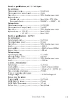
Страница 13: ...ions OUTPUT Current output Signal range span 0 20 mA Min signal range span 10 mA Max offset 50 of selec max value Load 600 Ω Load stability 0 01 of span 100 Ω Current limit 28 mA Voltage output Signal range span 0 10 VDC Min signal range span 500 mV Max offset 50 of selec max value Load 500 kΩ 2 wire 4 20 mA output Signal range 4 20 mA Load stability 0 01 of span 100 Ω Load resistance Vsupply 3 5 ...

Страница 14: ...S data for 5114 B2 channel 2 for 5114B3 Terminal 44 to 41 54 to 51 Uo 28 VDC Io 87 mADC Po 0 62 W Lo 4 2 mH Co 0 08 μF Terminal 42 43 to 41 52 53 to 51 Uo 7 5 VDC Io 6 0 mADC Po 11 25 mW Lo 200 mH Co 6 0 μF Marine approval Det Norske Veritas Ships Offshore Standard for Certification No 2 4 Ex I S approval ATEX 2014 34 EU DEMKO 99ATEX124571 EAC Ex TR CU 012 2011 RU C DK GB08 V 00410 Observed author...

Страница 15: ... inputs with internal CJC remember to order the CJC connectors type 5910 5910 Ex ch 1 and 5913 5913 Ex ch 2 Type Version Input Channels 5114 Standard A RTD TC R mA V mV Single A Double B ATEX Ex B RTD TC mV R 1 mA V mV 2 Channel 1 RTD TC mV R 3 Channel 2 mA V mV ...

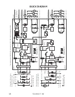
Страница 16: ...mm Supply 24 230 VAC 24 250 VDC 2 5 V 2 5 V Spec Output V Spec Output V RTD and lin R Conn wire 2 wire transm 3 wire potm Loop supply Vref Input gnd I V Out I V Out I Out I Out V Out V Out 2 wire output sup 2 wire output sup 2 wire output sup 2 wire output sup Supply Loop sup 17 1 V Loop sup 17 1 V Analogue Switch Analogue Switch Accessories 5910 CJC connector CH 1 5913 CJC connector CH 2 Channel ...

Страница 17: ...5114V107 UK 15 SELECTION OF INPUT TYPE 5114A Input JP 1 JP 2 JP 3 JP 4 Temperature channel 1 Temperature channel 2 1 1 1 1 Current voltage channel 1 Current voltage channel 2 2 2 2 2 ...

Страница 18: ...nic isolators for analog and digital signals as well as HART signals A wide product range with both loop powered and universal isolators featuring linearization inversion and scaling of output signals Isolation Interfaces for analogue and digital signals as well as HART signals between sensors I P converters frequency signals and control systems in Ex zone 0 1 2 and for some devices in zone 20 21 ...

Страница 19: ...m www prelectronics se sales se prelectronics com www prelectronics com sales uk prelectronics com www prelectronics com sales us prelectronics com www prelectronics cn sales cn prelectronics com www prelectronics be sales be prelectronics com Head office Denmark www prelectronics com PR electronics A S sales prelectronics dk Lerbakken 10 tel 45 86 37 26 77 DK 8410 Rønde fax 45 86 37 30 85 ...

Отзывы: