background image


17 


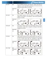
04: Zakres częstotliwości dla bypass 

Interfejs 

Ustawienia 


Parameter 2:

 Ustawienie akceptowalnej niskiej częstotliwości dla 

bypass. 

System - 50 Hz: Zakres ustawień jest od 46.0Hz do 49.0Hz. 

System - 60 Hz: Zakres ustawień jest od 56.0Hz do 59.0Hz. 

Domyślna wartość to 46.0Hz/56.0Hz. 

Parameter 3: 

Ustawienie akceptowalnej wysokiej częstotliwości 

dla bypass. 

50 Hz: Zakres ustawień jest w przedziale od 51.0Hz do 54.0 Hz.   

60 Hz: Zakres ustawień jest w przedziale od 61.0Hz do 64.0Hz. 

Domyślna wartość to 54.0Hz/64.0Hz. 


05: Zarezerwowane 

Interfejs 

Ustawienia 


Zarezerwowane


06: Zarezerwowane 

Interfejs 

Ustawienia 


Zarezerwowane


07: Zarezerwowane 

Interfejs 

Ustawienia 


Zarezerwowane


08: Tryb ustawień Bypass 

Interfejs 

Ustawienia 


Parametr 2:


OPN

: Bypass dozwolony. Kiedy jest wybrany, UPS uruchomi się w 

trybie Bypass w zależności od ustawienia bypass w ustawieniach. 

FBD

: Bypass niedozwolony. Kiedy jest wybrany, tryb ten nie 

zostanie uruchomiony w żadnej sytuacji. 

Parametr 3: 

ENA

: Bypass dozwolony. Kiedy jest wybrany, tryb Bypass jest 

PL 

Содержание VFI 10000 CT LCD

Страница 1: ...PowerWalker VFI 6000 CT LCD VFI 10000 CT LCD Manual Uninterruptible Power Supply System EN DE PL ...

Страница 2: ...g instructions in this manual strictly Save this manual properly and read carefully the following instructions before installing the unit Do not operate this unit before reading through all safety information and operating instructions carefully ...

Страница 3: ...REAR PANEL VIEW 5 2 3 SINGLE UPS INSTALLATION 6 2 4 SOFTWARE INSTALLATION 8 3 OPERATIONS 9 3 1 BUTTON OPERATION 9 3 2 LED INDICATORS AND LCD PANEL 9 3 3 AUDIBLE ALARM 11 3 4 SINGLE UPS OPERATION 11 3 5 ABBREVIATION MEANING IN LCD DISPLAY 14 3 6 LCD SETTING 14 3 7 OPERATING MODE STATUS DESCRIPTION 19 3 8 FAULT CODE 21 3 9 WARNING INDICATOR 21 4 TROUBLE SHOOTING 22 5 STORAGE AND MAINTENANCE 23 5 1 S...

Страница 4: ...nnect appliances or devices which would overload the UPS e g big motor type equipment to the UPS output sockets or terminal Place cables in such a way that no one can step on or trip over them Do not block air vents in the housing of UPS The UPS must be installed in a location with good ventilation Ensure enough space on each side for ventilation UPS has provided earthed terminal in the final inst...

Страница 5: ...uipment can reasonably be expected to cause the failure of the life support equipment or to significantly affect its safety or effectiveness is not recommended Do not use this equipment in the presence of a flammable anesthetic mixture with air oxygen or nitrous oxide Connect your UPS power module s grounding terminal to a grounding electrode conductor The UPS is connected to a DC energy source ba...

Страница 6: ...e mains Ensure that no liquid or other foreign objects can enter into the UPS system The UPS can be operated by any individuals with no previous experience 1 6 Standards Safety IEC EN 62040 1 EMI Conducted Emission IEC EN 62040 2 Category C3 Radiated Emission IEC EN 62040 2 Category C3 EMS ESD IEC EN 61000 4 2 Level 4 RS IEC EN 61000 4 3 Level 3 EFT IEC EN 61000 4 4 Level 4 SURGE IEC EN 61000 4 5 ...

Страница 7: ...ckage contents The shipping package contains One UPS One user manual One monitoring software CD One RS 232 cable option One USB cable One battery cable option NOTE Before installation please inspect the unit Be sure that nothing inside the package is damaged during transportation Do not turn on the unit and notify the carrier and dealer immediately if there is any damage or lacking of some parts P...

Страница 8: ...electric laws regulations and execute the following instructions by professional personnel 1 Make sure the mains wire and breakers in the building are in compliance with the standard of rated capacity of UPS to avoid the hazards of electric shock or fire NOTE Do not use the wall receptacle as the input power source for the UPS as its rated current is less than the UPS s maximum input current Other...

Страница 9: ...is not turned on before installation The UPS should not be turned on during wiring connection Do not try to modify the standard model to the long run model Particularly do not try to connect the standard internal battery to the external battery The battery type and voltage and numbers may be different If you connect them together it maybe causes the hazard of electric shock or fire Warning Only fo...

Страница 10: ...rent spec color position connection and conductance reliability of wire should be checked carefully Make sure the utility input output wiring is correct The current spec color position connection and conductance reliability of wire should be checked carefully Make sure the L N terminal is correct not reverse or short circuited 2 4 Software Installation For optimal computer system protection instal...

Страница 11: ...tton to display next selection in setting menu Mute Down Button Mute the alarm Press and hold the button more than 1s to mute the buzzer Please refer to section 3 4 Mute the buzzer for details Down key Press this button to display previous selection in setting menu Test Up Mute Down Button Press and hold the two buttons simultaneous more than 1s to enter escape the setting menu CVCF mode means con...

Страница 12: ...is disabled Output Battery voltage information Indicates the output voltage frequency or battery voltage Vac output voltage Vdc battery voltage Hz frequency Load information Indicates the load level by 0 25 26 50 51 75 and 76 100 Indicates overload Indicates the load or the output is short Mode operation information Indicates the UPS connects to the mains Indicates the battery is working Indicates...

Страница 13: ...tus Cover of maintain switch is open Fault Bus start failure Beeping continuously Yes Bus over Bus under Bus unbalance Inverter soft start failure High Inverter voltage Low Inverter voltage Inverter output short circuited Battery SCR short circuited Over temperature Overload 3 4 Single UPS Operation 1 Turn on the UPS with utility power supply in AC mode 1 After power supply is connected correctly ...

Страница 14: ...fter the overload is removed it will return to AC mode If the overload occurs 3 times in half hour the UPS will be locked in Bypass mode UPS can transfer to Line mode only by manual restart At this time if bypass is enabled the UPS will power to the load via bypass If bypass function is disabled or the input power is not within bypass acceptable range it will cut off output directly 4 Charge the b...

Страница 15: ...at least 1s and then the buzzer will beep once 2 Then UPS will cut off power to output and there is no display shown on the display panel 8 Mute the buzzer 1 To mute the buzzer please press the Mute button for at least 1s If you press it again after the buzzer is muted the buzzer will beep again 2 Some warning alarms can t be muted unless the error is fixed Please refer to section 3 3 for the deta...

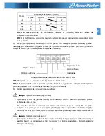
Страница 16: ...tives Refer to below table for the programs to set up Parameter 2 and parameter 3 are the setting options or values for each program Note Please select Up or Down button to change the programs or parameters Programs available list for parameter 1 Code Description Bypass AC CVCF Battery Battery Test 01 Output voltage Y 02 Output frequency Y 03 Voltage range for bypass Y 04 Frequency range for bypas...

Страница 17: ...0Hz 60 0Hz The output frequency is setting for 60 0Hz ATO If selected output frequency will be decided according to the latest normal utility frequency If it is from 46Hz to 54Hz the output frequency will be 50 0Hz If it is from 56Hz to 64Hz the output frequency will be 60 0Hz ATO is default setting Parameter 3 Frequency mode Setting output frequency at CVCF mode or non CVCF mode You may choose fo...

Страница 18: ...ass Interface Setting Parameter 2 Set the acceptable low frequency for bypass 50 Hz system Setting range is from 46 0Hz to 49 0Hz 60 Hz system Setting range is from 56 0Hz to 59 0Hz The default value is 46 0Hz 56 0Hz Parameter 3 Set the acceptable high frequency for bypass 50 Hz Setting range is from 51 0Hz to 54 0 Hz 60 Hz Setting range is from 61 0Hz to 64 0Hz The default value is 54 0Hz 64 0Hz ...

Страница 19: ...ass is not allowed Manual bypass means users manually operate UPS for Bypass mode For example pressing OFF button in AC mode to turn into Bypass mode 09 Battery maximum discharge time setting Interface Setting Parameter 3 000 999 Set the maximum discharge time from 0 min to 999 min UPS will shut down to protect battery after discharge time arrives The default value is 990 min DIS Disable battery d...

Страница 20: ... to calibrate inverter voltage Parameter 3 The voltage setting range is from 0V to 6 4V The default value is 0V 16 Floating charger voltage adjustment Interface Setting Parameter 2 you may choose Add or Sub to adjust floating charger voltage Parameter 3 the voltage range is from 0V to 8V the default value is 0V 17 Constant charger voltage adjustment Interface Setting Parameter 2 you may choose Add...

Страница 21: ... Backup time calibration Interface Setting Parameter 3 Calibrate the displayed backup time by adjusting this multiplier factor The formulation is listed below Displayed backup time Original calculated backup time x Multiplier factor The default value of multiplier factor is 1 0 and the setting range is from 0 5 to 2 3 7 Operating Mode Status Description Operating mode status AC mode Description Wh...

Страница 22: ...s enabled turn off the UPS and it will enter Bypass mode Alarm beeps every two minutes LCD display Battery Test Description When UPS is in AC mode or CVCF mode press Test key for more than 1s Then the UPS will beep once and start Battery Test The line between I P and inverter icons will blink to remind users This operation is used to check the battery status LCD display Fault status Description Wh...

Страница 23: ...None Over temperature 41 None Inverter soft start failure 11 None Overload 43 High Inverter voltage 12 None 3 9 Warning Indicator Warning Icon flashing Alarm Battery low Beeping every second Overload Beeping twice every second Battery unconnected Beeping every second Over charge Beeping every second EPO enable Beeping every second Over temperature Beeping every second Charger failure Beeping every...

Страница 24: ...overloads the UPS is locked in the Bypass mode Connected devices are fed directly by the mains Remove excess loads from UPS output first Then shut down the UPS and restart it Fault code is shown as 43 The icon lights on LCD display and alarm beeps continuously UPS is overload too long and becomes fault Then UPS shut down automatically Remove excess loads from UPS output and restart it Fault code i...

Страница 25: ...e required precautionary measures may replace batteries and supervise operations Unauthorized persons must be kept well away from the batteries Verify that no voltage between the battery terminals and the ground is present before maintenance or repair In this product the battery circuit is not isolated from the input voltage Hazardous voltages may occur between the battery terminals and the ground...

Страница 26: ...A Adjustable Charging Voltage 218 4V 1 273V 1 218 4V 1 273V 1 Long run Model Battery Type Depending on applications Numbers 16 20 Charging Current Default 4 A 10 Max 1A 2A 4A 6A Adjustable 6A is only available for 16pcs batteries Charging Voltage 218 4V 1 based on 16pcs batteries PHYSICAL Standard Model Dimension DXWXH mm 369 x 190 x 688 442x 190 x 688 Net Weight kgs 61 74 66 76 Long run Model Dim...

Страница 27: ...PowerWalker VFI 6000 CT LCD VFI 10000 CT LCD Bedienungsanleitung Unterbrechungsfreie Stromversorgung DE ...

Страница 28: ...unbedingt beachtet werden Bewahren sie diese Anleitung gut auf und lesen Sie die folgenden Hinweise vor der Installation sorgfältig durch Nehmen Sie das Gerät erst in Betrieb wenn Sie alle Sicherheitshinweise und die Bedienungsanleitung sorgfältig durchgelesen haben ...

Страница 29: ...UND BETRIEB 6 2 1 AUSPACKEN UND ÜBERPRÜFEN 6 2 2 HINTERE KONSOLENANSICHT 6 2 3 USV EINZELINSTALLATION 7 2 4 SOFTWARE INSTALLATION 9 3 BETRIEB 10 3 1 TASTENBEDIENUNG 10 3 2 LED ANZEIGE UND LCD PANEL 10 3 3 AKUSTISCHER ALARM 12 3 4 USV EINZELPLATZBETRIEB 12 3 5 BEDEUTUNG DER AUF DEM LCD DISPLAY ANGEZEIGTEN ABKÜRZUNGEN 16 3 6 LCD EINSTELLUNG 16 3 7 BETRIEBSMODUS STATUSBESCHREIBUNG 21 3 8 FAULT CODE 2...

Страница 30: ...strahlung aus Halten Sie die Ventilationsöffnungen des USV Gehäuses frei 1 3 Installation Schließen Sie keine Geräte an die Ausgang Buchse oder Klemmen an die Die USV überlasten z B Geräte hoher Leistung Platzieren Sie das Kabel so dass niemand darauf treten oder darüber stolpern kann Halten Sie die Ventilationsöffnungen des USV Gehäuses frei Die USV muss an einem Ort mit guter Belüftung installie...

Страница 31: ...3 ...

Страница 32: ...es zugemutet wird kann dazu führen dass diese Geräte versagen oder deren Sicherheit oder Wirksamkeit beeinträchtigt wird Verwenden Sie dieses Gerät nicht in der Nähe von einer brennbaren Mischung von Anästhetika mit Luft Sauerstoff oder Stickstoffoxid Verbinden Sie Ihren USV Erdungsanschluss des Leistungsmoduls mit einem Erdungsleiter Die USV ist mit einer DC Energiequelle Batterie verbunden Die A...

Страница 33: ...n Stellen Sie sicher dass keine Flüssigkeit oder sonstige Fremdkörper in die USV gelangen Die USV kann von allen Personen ohne Vorkenntnisse bedient werden 1 6 Standards Sicherheit IEC EN 62040 1 EMI Abgeleitete Sendeleistung IEC EN 62040 2 Kategorie C3 Strahlungsemission IEC EN 62040 2 Kategorie C3 EMS ESD IEC EN 61000 4 2 Stufe 4 RS IEC EN 61000 4 3 Stufe 3 EFT IEC EN 61000 4 4 Stufe 4 ÜBERSPANN...

Страница 34: ...halt Das Paket enthält Eine UPS Eine Bedienungsanleitung Eine Monitoring Software CD Ein RS 232 Kabel optional Ein USB Kabel Ein Batteriekabel optional HINWEIS Inspizieren Sie das Gerät vor der Installation Vergewissern Sie sich dass kein Teil in der Packung während des Transport beschädigt wurde Falls ein Teil fehlt oder schadhaft ist schalten Sie die Einheit nicht ein und informieren Sie den Tra...

Страница 35: ... geltenden Bestimmungen unter Beachtung der örtlichen Vorschriften von einem Fachmann durchzuführen 1 Stellen Sie sicher dass Nennleistung des Netzkabels und der Schalter ausreichend sind um Stromschlägen und Brandgefahr vorzubeugen HINWEIS Schließen Sie die USV nicht an die Wandsteckdose an wenn die Nennleistung geringer ist als der maximale Eingangsstrom der USV Andernfalls kann die Steckdose du...

Страница 36: ...stallation ausgeschaltet ist Die USV sollte während der Verdrahtung nicht eingeschaltet werden Versuchen Sie nicht ein Standardmodell in ein Long run Modell zu verändern Versuchen Sie nicht die eingebaute Batterie an eine externe Batterie anzuschließen Batterietyp und Spannung können unterschiedlich sein Wenn Sie sie miteinander verbinden kann das zu Stromschlägen und Brandgefahr führen Warnung nu...

Страница 37: ...sgeführt ist Die aktuelle Spezifikation Farbe Position Anschluss und Leitfähigkeit sollte sorgfältig überprüft werden Stellen Sie sicher dass die Ein Ausgangsverdrahtung korrekt ist Die aktuelle Spezifikation Farbe Position Anschluss und Leitfähigkeit sollte sorgfältig überprüft werden Stellen Sie sicher dass die L N korrekt und nicht umgekehrt oder kurzgeschlossen ist 2 4 Software Installation In...

Страница 38: ... Taste um die nächste Auswahl im Einstellungsmenü anzuzeigen Mute Down Button Stummschalten des Alarms Drücken und halten Sie die Taste für mindestens 1 Sekunde um den Signalton abzuschalten Siehe Abschnitt 3 4 Alarm stummschalten für Einzelheiten Down Taste Drücken Sie diese Taste um die vorherige Auswahl im Einstellungsmenü anzuzeigen Test Up Mute Down Button Drücken und halten Sie die Tasten En...

Страница 39: ...rmation Zeigt die Ausgangsspannung Frequenz oder Akkuspannung an Vac Ausgangsspannung Vdc Akkuspannung Hz Frequenz Last Information Zeigt die Last in 0 25 26 50 51 75 und 76 100 an Zeigt Überlastung an Zeigt einen Kurzschluss in Last und Ausgang an Betriebsmodus Information Zeigt an dass das die USV an das Stromnetz angeschlossen ist Zeigt an dass der Akku einwandfrei funktioniert Zeigt an dass de...

Страница 40: ...n Lüfterfehler Übertemperatur Ladegerät Ausfall Überlast 3 Mal in 30min EPO Status Abdeckung des Hauptschalters geöffnet Fehler Bus Fehlstart Dauer Piepton Ja Bus über Bus unter Bus Ungleichgewicht Inverter Soft Start Ausfall Hohe Inverter Spannung Niedrige Inverter Spannung Inverter Ausgang kurzgeschlossen Akku SCR kurzgeschlossen Übertemperatur Überlast 3 4 USV Einzelplatzbetrieb 1 USV Stromvers...

Страница 41: ... 3 Ist die USV überlastet ertönt zweimal in der Sekunde ein Akustischer Warnton 4 Ist die USV überlastet beseitigen unverzüglich die Lasten Es wird empfohlen die Gesamtlast auf die USV unter 80 der nominalen Leistungskapazität zu halten um eine Überlastung der Systemsicherheit zu vermeiden 5 Ist die Überlastzeit überschritten schaltet die USV automatisch in den Bypass Modus Nachdem die Überlast en...

Страница 42: ...ach dem Ausschalten dass die USV im Bypass Modus arbeitet und die Gefahr einer Stromunterbrechung für die angeschlossenen Geräte besteht 2 Im Bypass Modus ist immer noch Ausgangsspannung in der USV vorhanden Um den Ausgang auszuschalten schalten Sie den Leitungseingang ab bei einer dualen Eingabeeinheit auch den Bypass Schalter abschalten Einige Sekunden später wird auf dem Display angezeigt dass ...

Страница 43: ...halten Sie die USV nicht ein bevor die Probleme gelöst sind Wenn die Probleme nicht behoben werden können wenden Sie sich bitte unverzüglich an den Händler oder den Kundendienst 3 Trennen Sie bitte im Notfall unverzüglich die Verbindung zum Programm externen Batterie und Ausgang um größere Schäden zu vermeiden ...

Страница 44: ...t für ein alternatives Programm Beachten Sie untenstehende Tabelle bei der Einstellung Parameter 2 und Parameter 3 geben die Einstelloptionen oder Werte für jedes Programm wieder HINWEIS Bitte wählen Sie die Up oder Down Taste um die Programme oder Parameter zu ändern Programm Verfügbarkeitsliste Parameter 11 Code Beschreibung Bypass AC CVCF Battery Battery Test 01 Ausgangsspannung Y 02 Ausgangsfr...

Страница 45: ...60 0Hz Einstellung der Ausgangsfrequenz für 60 0Hz ATO Wenn ausgewählt wird die Ausgangsfrequenz entsprechend der neuesten normalen Gebrauchsfrequenz entschieden Bei 46Hz bis 54Hz ist die Ausgangsfrequenz 50 0Hz Bei 56Hz bis 64Hz ist die Ausgangsfrequenz 60 0Hz ATO ist die Standardeinstellung Parameter 3 Frequenzmodus Einstellung der Ausgangsfrequenz im CVCF Modus oder nicht CVCF Modus Sie können ...

Страница 46: ...tstelle Einstellung Parameter 2 Stellen Sie die tolerable Niedrigfrequenz für den Bypass ein 50 Hz System Einstellungsbereich ist von 46 0Hz bis 49 0Hz 60 Hz System Einstellungsbereich ist von 56 0Hz bis 59 0Hz Der Standardwert liegt bei 46 0Hz 56 0Hz Parameter 3 Stellen Sie die tolerable Höchstfrequenz für Bypass ein 50 Hz Einstellungsbereich ist von 51 0Hz bis 54 0 Hz 60 Hz Einstellungsbereich i...

Страница 47: ... Anwender die USV manuell in den Bypass Modus umstellen kann Zum Beispiel durch Drücken der OFF Taste vom AC Modus in den Bypass Modus wechseln 09 Einstellung maximale Batterieentladungszeit Schnittstelle Einstellung Parameter 3 Parameter 3 000 999 Stellen Sie die maximale Entladezeit von 0 min bis 999 min ein Die USV schaltet bei einer festgelegten Spannungsschwelle ab um die Batterie vor Tiefent...

Страница 48: ...Spannung des Inverters einstellen Parameter 3 Der Spannungsbereich ist von 0V bis 6 4V und der Standardwert liegt bei 0V 16 Ladegerät Spannungsanpassung Schnittstelle Einstellung Parameter 2 Sie können mit Add oder Sub die Spannung des Ladegeräts einstellen Parameter 3 Der Spannungsbereich ist von 0V bis 8V und der Standardwert liegt bei 0V 17 Konstante Ladegerät Spannungsanpassung Schnittstelle E...

Страница 49: ...endet 20 Backup Zeitkalibrierung Schnittstelle Einstellung Parameter 3 Kalibrieren Sie die angezeigten Backup Zeit durch einstellen des Multiplikationsfaktors Die Formulierung ist nachstehend aufgeführt Anzeige Backup Zeit Ursprüngliche Berechnung Backup Zeit x Multiplikationsfaktor Der Standardwert des Multiplikationsfaktors beträgt 1 0 und der Einstellbereich reicht von 0 5 bis 2 3 7 Betriebsmod...

Страница 50: ...eaktiviert ist schalten Sie die USV aus und sie wechselt in den Bypass Modus Das Alarmsignal ertönt alle zwei Minuten LCD Display Batterietest Beschreibung Ist die USV im AC oder CVCF Modus drücken Sie für mehr als 1 Sekunden die Test Taste Es ertönt ein Signalton und der Batterietest beginnt Die Verbindung zwischen I P und Inverter Symbol blinkt um den User daran zu erinnern Diese Funktion wird v...

Страница 51: ...04 Keines Übertemperatur 41 Keines Inverter Softstart Fehler 11 Keines Überlast 43 Inverter Überspannung 12 Keines 3 9 Warnanzeige Warnung Symbol blinkt Alarm Batterie schwach Ertönt jede Sekunde Überlastung Ertönt zweimal in jeder Sekunde Batterie ist nicht angeschlossen Ertönt jede Sekunde Überspannung Ertönt jede Sekunde EPO aktiviert Ertönt jede Sekunde Übertemperatur Ertönt jede Sekunde Ladef...

Страница 52: ...gt Entfernen Sie zuerst überschüssige Lasten vom USV Ausgang Dann fahren Sie die USV herunter und starten erneut Der Fehlercode 43 erscheint auf dem Display Das Symbol blinkt auf der LED Anzeige und der Alarm ertönt kontinuierlich Die USV ist zu lange überlastet und hat einen Fehler Die USV fährt automatisch herunter Entfernen Sie das überschüssige Lasten vom USV Ausgang und starten Sie erneut Der...

Страница 53: ... und Kenntnis über die geforderten Vorsichtsregeln durchzuführen und zu überwachen Unbefugte Personen sind von den Batterien fernzuhalten Stellen Sie vor Wartungs und Reparaturarbeiten sicher dass keine Spannung zwischen Batterieanschlüssen und der Erdung vorhanden ist In diesem Produkt ist der Batteriestromkreis nicht von der Eingangsspannung isoliert Zwischen den Batterieanschlüssen und der Erdu...

Страница 54: ... Max 1A 2A einstellbar Ladespannung 218 4V 1 273V 1 218 4V 1 273V 1 Long run Modelle Batterie Typ Je nach Anwendungen Nummern 16 20 Ladestrom Standard 4 A 10 Max 1A 2A 4A 6A einstellbar 6A ist nur für 16 Batterien verfügbar Ladespannung 218 4V 1 basierend auf 16pcs Batterien PHYSIKALISCH Standard Modelle Abmessung DXWXH mm 369 x 190 x 688 442x 190 x 688 Nettogewicht kgs 61 74 66 76 Long run Modell...

Страница 55: ...PowerWalker VFI 6000 CT LCD VFI 10000 CT LCD Instrukcja obsługi Awaryjny system zasilania PL PL ...

Страница 56: ...cji wraz z zasadami postępowania Używaj poprawnie poniższą instrukcję oraz uważnie przeczytaj poniższe zalecenia przed instalacją urządzenia Nie korzystaj z UPS przed uważnym przeczytaniem wszystkich informacji dotyczących bezpieczeństwa oraz instrukcji obsługi PL ...

Страница 57: ... PANELU 5 2 3 POJEDYNCZE PODŁĄCZENIE ZASILANIA UPS 6 2 4 INSTALACJA OPROGRAMOWANIA 8 3 PRACA 9 3 1 FUNKCJE PRZYCISKÓW 9 3 2 DIODY LED I PANEL LCD 9 3 3 SYGNAŁY DŹWIĘKOWE 11 3 4 POJEDYNCZY TRYB PRACY 11 3 5 ZNACZENIE SKRÓTÓW NA WYŚWIETLACZU LCD 14 3 6 USTAWIENIA LCD 15 3 7 TRYBY PRACY OPIS STATUSÓW 20 3 8 KODY BŁĘDÓW 22 3 9 OSTRZEŻENIA WSKAŹNIKÓW 22 4 ROZWIĄZYWANIE PROBLEMÓW 23 5 PRZECHOWYWANIE I K...

Страница 58: ...ryzacyjny do gniazd wyjściowych urządzenia lub terminalu Podłącz kable w taki sposób żeby wyeliminować ryzyko nadepnięcia lub potknięcia się o nie Nie zasłaniaj otworów wentylacyjnych na obudowie zasilacza UPS musi zostać umieszczony w pomieszczeniu z dobrą wentylacją Upewnij się że urządzenie posiada wystarczająco dużo wolnego miejsca z każdej strony UPS dostarcza terminal uziemiający połączenia ...

Страница 59: ...ub ich skuteczność Nie należy używać tego urządzenia w otoczeniu tlenku lub podtlenku azotu palnych mieszanin oraz środków anestetycznych w powietrzu Podłącz uziemienie modułu zasilającego do przewodu uziemienia UPS jest podłączony do źródła prądu stałego bateria Terminale wyjściowe mogą być pod napięciem nawet gdy kiedy urządzenie nie jest podłączone do gniazda sieci elektrycznej budynku Przed ro...

Страница 60: ...S może być obsługiwany przez osoby bez wcześniejszego doświadczenia 1 6 Standardy Bezpieczeństwo IEC EN 62040 1 EMI Emisja przewodzenia IEC EN 62040 2 Kategoria C3 Emisja promieniowania IEC EN 62040 2 Kategoria C3 EMS ESD IEC EN 61000 4 2 Poziom 4 RS IEC EN 61000 4 3 Poziom 3 EFT IEC EN 61000 4 4 Poziom 4 SURGE IEC EN 61000 4 5 Poziom 4 CS IEC EN 61000 4 6 Poziom 3 Częstotliwość sieciowa pola magn...

Страница 61: ...ekcja Rozpakuj opakowanie oraz sprawdź jego zawartość Opakowanie zawiera UPS Instrukcję obsługi Oprogramowanie monitorujące na płycie CD Kabel RS 232 opcjonalnie Kabel USB Kabel baterii opcjonalnie INFO Sprawdź UPS po otrzymaniu Jeśli opakowanie nosi ślady uszkodzenia podczas transportu nie rozpakowuj urządzenia powiadom przewoźnika i sprzedawcę Proszę trzymać oryginalne opakowanie w bezpiecznym m...

Страница 62: ...ja i okablowanie muszą być wykonane zgodnie z lokalnymi przepisami elektrycznym Instalacja musi być wykonana przez wykwalifikowany personel 1 Upewnij się że przewód zasilający i bezpieczniki w budynku są zgodne ze standardem pojemności znamionowej zasilacza aby uniknąć zagrożeń związanych z porażeniem prądem lub pożarem INFO Nie korzystaj jako źródła zasilania gniazda naściennego ponieważ jego nat...

Страница 63: ...nik pomiędzy terminalem wyjściowym a obciążeniem Bezpiecznik powinien posiadać funkcję ochronną natężenia prądu jeśli to konieczne 6 Włóż z powrotem małą pokrywę do panelu tylnego Uwaga Tylko dla standardowego modelu Upewnij się że UPS nie jest uruchomiony przed instalacją UPS nie powinien by włączony podczas podłączania okablowania Nie modyfikuj zawartości standardowego modelu do modelu long run ...

Страница 64: ...rii Upewnij się że prawidłowo podłączona jest biegunowość baterii Nieprawidłowe podłączenie może spowodować trwałe uszkodzenie UPS Upewnij się że przewody uziemienia oraz ich instalacja jest prawidłowa Obecną specyfikację kolor położenie połączenie i przewodności przewodu należy dokładnie sprawdzić Upewnij się że przewody wejściowe i wyjściowe są prawidłowe Obecną specyfikację kolor położenie połą...

Страница 65: ... wyświetlić następny wybór w menu ustawień Mute Przycisk Down Wyciszenie alarmu Naciśnij i przytrzymaj przycisk dłużej niż 0 5s aby wyciszyć dzwonek Proszę odnieść się do sekcji 3 4 Wyciszenie dzwonka po szczegóły Przycisk Down Naciśnij ten przycisk aby wyświetlić poprzedni wybór w menu ustawień Test Przyciski Up Mute Down Naciśnij i przytrzymaj oba przyciski jednocześnie więcej niż 1s aby wejść w...

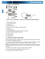
Страница 66: ...zony Informacja o napięciu wyjścia i baterii Wskazuje napięcie wyjścia częstotliwości lub napięcia baterii Vac napięcie wyjściowe Vdc napięcie baterii Hz częstotliwość Informacja o obciążeniu Wskazuje informację o obciążeniu UPS 0 25 26 50 51 75 76 100 Wskazuje że UPS jest przeciążony Wskazuje że nastąpiło zwarcie na wyjściu UPS Informacja o trybach pracy Wskazuje że UPS jest podłączony do sieci W...

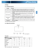
Страница 67: ...owy co sekundę Niepodłączona bateria Przeciążenie Aktywne EPO Awaria wentylatora Wysoka tmp Awaria ładowarki Przeładowanie 3 razy w przeciągu 30 minut Status EPO Osłona przełącznika konserwacyjnego jest otwarta Błąd Awaria startu Bus Ciągły sygnał Tak Bus over Bus under Niezbalansowany Bus Awaria soft startu inwertera Wysokie napięcie inwertera Niskie napięcie inwertera Zwarcie wyjścia inwertera Z...

Страница 68: ... jest przeciążony należy natychmiast usunąć niektóre obciążenia Zaleca się aby łączne obciążenie podłączone do zasilacza było mniejsze niż 80 jego nominalnej pojemności aby zapobiec przeciążeniu dla bezpieczeństwa systemu 5 Jeżeli przeciążenie przekroczy akceptowalny czas wyszczególniony w specyfikacji w trybie AC UPS automatycznie przejdzie w tryb Bypass Po tym jak obciążenie zostanie usunięte ur...

Страница 69: ...e napięcie z sieci elektrycznej bypass do gniazda wyjściowego oraz terminalu nawet po wyłączeniu UPS inwerter INFO 2 Po wyłączeniu UPS należy pamiętać że UPS pracuje w trybie Bypass istnieje ryzyko utraty zasilania dla podłączonych urządzeń 2 W trybie Bypass napięcie wyjściowe UPS jest nadal obecne W celu odcięcia wyjścia wyłącz bezpiecznik wejściowy Kilka sekund później nic nie powinno wyświetlać...

Страница 70: ...związaniem problemu Jeśli problem nie może być ustalony lub naprawiony należy natychmiast skontaktować się z dystrybutorem lub obsługą techniczną 3 W razie niebezpieczeństwa należy natychmiast odciąć połączenie z urządzeniem zewnętrzną baterią i wyjściem UPS aby uniknąć większego ryzyka lub zagrożenia 3 5 Znaczenie skrótów na wyświetlaczu LCD Skrót Informacje na wyświetlaczu Znaczenie ENA Włączony...

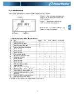
Страница 71: ...cia dla bypass Y 04 Zakres częstotliwości dla bypass Y 05 Zarezerwowane 06 Zarezerwowane 07 Zarezerwowane 08 Tryb ustawień Bypass Y Y 09 Maksymalne ustawienie czasu rozładowania baterii Y Y Y Y Y 10 Zarezerwowane 11 Zarezerwowane 12 Zarezerwowane 13 Kalibracja napięcia baterii Y Y Y Y Y 14 Zarezerwowane 15 Kalibracja napięcia inwertera Y Y Y 16 Płynna regulacja napięcia ładowarki Y Y Y Y Y 17 Stał...

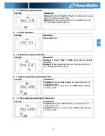
Страница 72: ...2 opcje w parametrze 3 CF Ustawienie UPS w trybie CVCF Jeśli jest wybrany częstotliwość wyjściowa będzie ustalona na poziomie 50Hz lub 60Hz w zależności od ustawienia parametru 2 Częstotliwość wejściowa może być od 46Hz do 64hz NCF Ustawienie UPS w zwykłym trybie nie CVCF Jeśli jest wybrany częstotliwość wyjściowa zsynchronizuje się z częstotliwością wejściową w przedziale 46 54 Hz przy 50Hz lub 5...

Страница 73: ...4 0 Hz 60 Hz Zakres ustawień jest w przedziale od 61 0Hz do 64 0Hz Domyślna wartość to 54 0Hz 64 0Hz 05 Zarezerwowane Interfejs Ustawienia Zarezerwowane 06 Zarezerwowane Interfejs Ustawienia Zarezerwowane 07 Zarezerwowane Interfejs Ustawienia Zarezerwowane 08 Tryb ustawień Bypass Interfejs Ustawienia Parametr 2 OPN Bypass dozwolony Kiedy jest wybrany UPS uruchomi się w trybie Bypass w zależności o...

Страница 74: ...Bypass 09 Maksymalne ustawienie czasu rozładowania baterii Interfejs Ustawienia Parametr 3 000 999 przedziale 0 999 minut UPS wyłączy się automatycznie w celu ochrony baterii po jej rozładowaniu Domyślną wartością jest 990min DIS Wyłączenie ochrony rozładowania baterii zależy od jej pojemności 10 Zarezerwowane Interfejs Ustawienia Zarezerwowane 11 Zarezerwowane Interfejs Ustawienia Zarezerwowane 1...

Страница 75: ...z Add lub Sub aby skalibrować napięcie konwertera Parametr 3 Zakres napięcia mieści się w przedziale od 0V do 6 4V Wartością domyślną jest 0V 16 Płynna regulacja napięcia ładowarki Interfejs Ustawienia Parametr 2 Wybierz Add lub Sub aby dostosować płynnie napięcie ładowarki Parametr 3 zakres napięcia wynosi od 0V do 8V Domyślną wartością jest 0V 17 Stała regulacja częstotliwości ładowarki Interfej...

Страница 76: ... od 1 do 6 Domyślną wartością jest 1 grupa Parametry te są do obliczenia czasu podtrzymania baterii 20 Kalibracja czasu podtrzymania Interfejs Ustawienia Parametr 3 Skalibruj wyświetlaczy czas podrzymania przez dostosowanie tego mnożnika Formuła jest wymieniona poniżej Wyświetlaczy czas podtrzymania Oryginalnie wyliczony czas podtrzymania x mnożnik Domyślną wartością mnożnika jest 1 0 a zakres ust...

Страница 77: ...ryb Bypass Opis Gdy napięcie wejściowe mieści się w dopuszczalnym zakresie a bypass jest dozwolony wyłącz UPS a on przejdzie w tryb Bypass Alarm będzie powtarzany co 2 minuty Wyświetlacz LCD Test baterii Opis Kiedy UPS jest w trybie AC lub CVCF naciśnij przycisk Test dłużej niż 1s Następnie UPS wyda sygnał i rozpocznie Test baterii Ikony sieci między I P oraz inwertera będą migać dla powiadomienia...

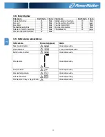
Страница 78: ...mperatura 41 Brak Awaria soft startu inwertera 11 Brak Przeładowanie 43 Wysokie napięcie inwertera 12 Brak 3 9 Ostrzeżenia wskaźników Ostrzeżenie Ikona migająca Alarm Niski poziom baterii Co każdą sekundę Przeładowanie 2 razy co każdą sekundę Battery unconnected Co każdą sekundę Przeciążenie Co każdą sekundę Aktywne EPO Co każdą sekundę Wysoka temperatura Co każdą sekundę Awaria ładowarki Co każdą...

Страница 79: ...lokowany jest w trybie Bypass Podłączone urządzenia są zasilane bezpośrednio z sieci zasilającej Odłącz urządzenia które przeciążają UPS Następnie wyłącz UPS i zrestartuj go Wyświetlany jest kod błędu 43 Świeci się ikona na ekranie LCD oraz powtarzany jest ciągły sygnał UPS jest przeciążony zbyt długo Następnie UPS wyłączy się automatycznie Odłącz urządzenia które przeciążają UPS i zrestartuj go P...

Страница 80: ...środków ostrożności przy takim zabiegu mogą zastąpić aktualne baterie i koordynować taką zmianę dala Baterie należy przechowywać w bezpiecznym miejscu przed osobami nieupoważnionymi Upewnij się że nie ma napięcia pomiędzy terminalem baterii i uziemienia przed konserwacją lub naprawą W tym produkcie obwód baterii nie jest odizolowany od napięcia wejściowego Niebezpieczne napięcia mogą wystąpić pomi...

Страница 81: ...wane Napięcie ładowania 218 4V 1 273V 1 218 4V 1 273V 1 Model Long run Typ W zależności od zastosowań aplikacji Liczba 16 20 Natężenie ładowania Domyślnie 4 A 10 Max 1A 2A 4A 6A Regulowane 6A jest dostępne tylko dla 16 szt baterii Napięcie ładowania 218 4V 1 w oparciu 16 szt baterii WYMIARY I WAGA Standardowy Model Wymiary D x S x W mm 369 x 190 x 688 442 x 190 x 688 Waga netto kg 61 74 66 76 Mode...

Отзывы: