17
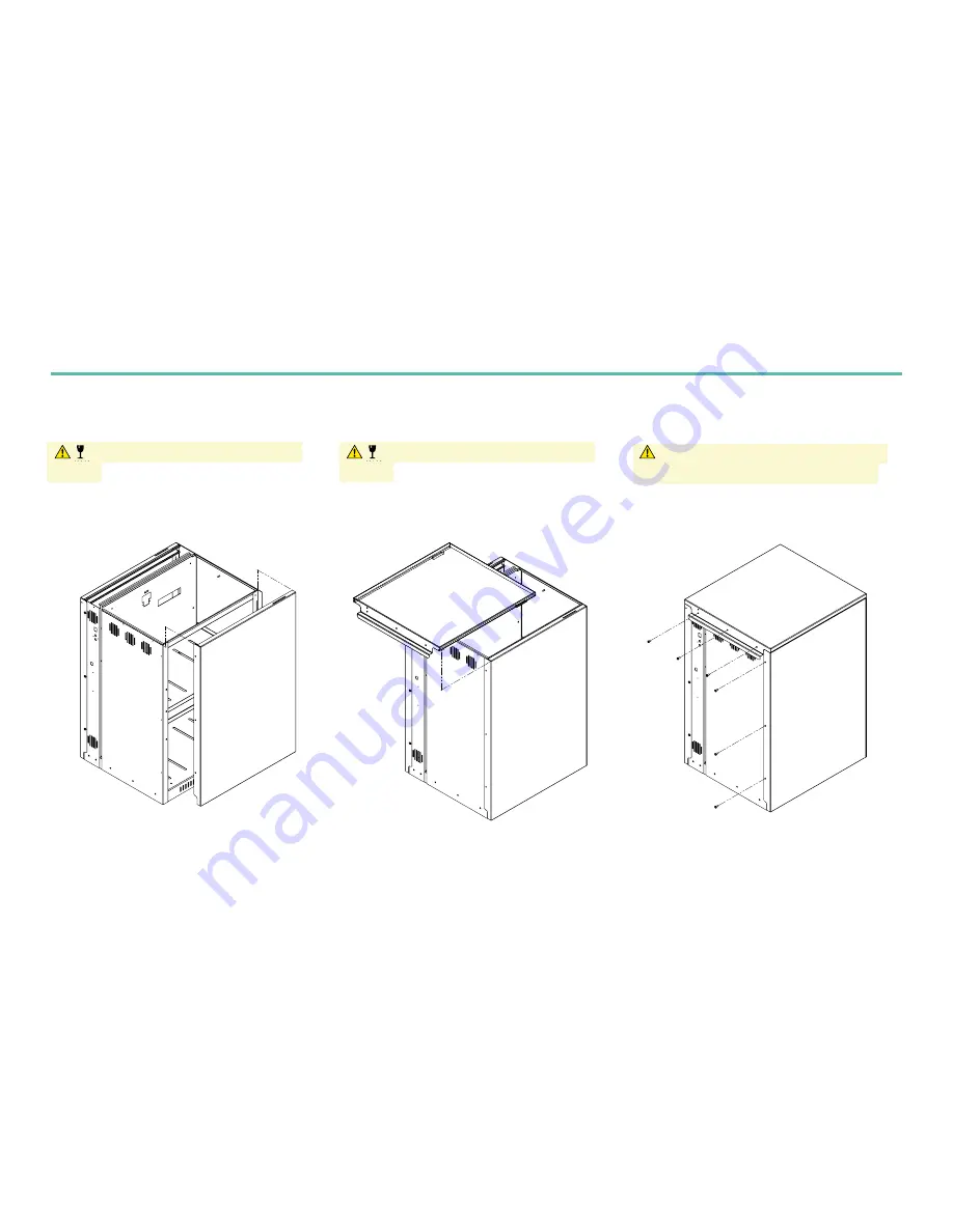
Part 5: Replacing the Powervault G200 panels
i
Slide left side panel down to reattach. Make sure
both hooks on the panel are placed inside the slots.
Caution: delicate wiring connected to the
top cover. Ensure you connect the earth wire to
the top panel before you slide it back into place.
ii
Slide top panel into place making sure to insert the
hooks on the panel into the slots on the frame.
Caution: delicate wiring connected to the
top cover. Ensure you connect the earth wire to
the top panel before you slide it back into place.
iii
Replace the screws that you removed at the
beginning of the installation to secure the panels.
Caution: the earth wire is a safety feature and
all care must be taken to ensure good contact.
A
A
B
B
C
C
D
D
E
E
F
F
8
8
7
7
6
6
5
5
4
4
3
3
2
2
1
1
DRAWN
CHK'D
UNLESS OTHERWISE SPECIFIED:
DIMENSIONS ARE IN MILLIMETERS
SURFACE FINISH:
TOLERANCES:
LINEAR: +/- 0.05
ANGULAR: +/- 0.5
FINISH:
DEBURR AND
BREAK SHARP
EDGES
NAME
SIGNATURE
DATE
MATERIAL:
DO NOT SCALE DRAWING
REVISION
TITLE:
DWG NO.
SCALE:1:20
SHEET 1 OF 5
A3
MATERIAL THICKNESS:
C. Tyler
A. Locke
10/05/17
10/05/17
Dynamic Marine Engineering
PV1_A00_8_Full 500 Assembly
Full 500 Assembly
1
mm
A
A
B
B
C
C
D
D
E
E
F
F
8
8
7
7
6
6
5
5
4
4
3
3
2
2
1
1
DRAWN
CHK'D
UNLESS OTHERWISE SPECIFIED:
DIMENSIONS ARE IN MILLIMETERS
SURFACE FINISH:
TOLERANCES:
LINEAR: +/- 0.05
ANGULAR: +/- 0.5
FINISH:
DEBURR AND
BREAK SHARP
EDGES
NAME
SIGNATURE
DATE
MATERIAL:
DO NOT SCALE DRAWING
REVISION
TITLE:
DWG NO.
SCALE:1:20
SHEET 2 OF 5
A3
MATERIAL THICKNESS:
C. Tyler
A. Locke
10/05/17
10/05/17
Dynamic Marine Engineering
PV1_A00_8_Full 500 Assembly
Full 500 Assembly
1
mm
A
A
B
B
C
C
D
D
E
E
F
F
8
8
7
7
6
6
5
5
4
4
3
3
2
2
1
1
DRAWN
CHK'D
UNLESS OTHERWISE SPECIFIED:
DIMENSIONS ARE IN MILLIMETERS
SURFACE FINISH:
TOLERANCES:
LINEAR: +/- 0.05
ANGULAR: +/- 0.5
FINISH:
DEBURR AND
BREAK SHARP
EDGES
NAME
SIGNATURE
DATE
MATERIAL:
DO NOT SCALE DRAWING
REVISION
TITLE:
DWG NO.
SCALE:1:20
SHEET 3 OF 5
A3
MATERIAL THICKNESS:
C. Tyler
A. Locke
10/05/17
10/05/17
Dynamic Marine Engineering
PV1_A00_8_Full 500 Assembly
Full 500 Assembly
1
mm
FIGURE 20
FIGURE 19
FIGURE 18


