background image

1" x 30" BELT SANDER PARTS LIST

9

PARTS LIST

9

Key#

Part#

Description

Specification

1

BD1030001

Side Cover

2

BD1030002

Cover Knob

3

BD1030003

Sanding Belt

25.4*762mm/80#

4

BD1030004

Rear Driven Wheel

4.1

BD1030004.1

C-Ring

Φ

15

4.2

BD1030004.2

Pulley

4.3

BD1030004.3

Bearing

6202-2Z

4.4

BD1030004.4

Tension Axle

5

BD1030005

Rear Driven Wheel

5.1

BD1030005.1

C-Ring

Φ

15

5.2

BD1030005.2

Pulley

5.3

BD1030005.3

Bearing

6202-2Z

5.4

BD1030005.4

Pulley Axle

6

BD1030006

Set Screw

M6X10

7

BD1030007

Motor Pulley

8

BD1030008

Bolt

M8X25

9

BD1030009

Screw

M6X12

10

BD1030010

Nut

M10

11

BD1030011

Washer

Φ

10

12

BD1030012

Frame

13

BD1030013

Set Screw

M6X8

14

BD1030014

Bolt

M4X10

15

BD1030015

Washer

Φ

4

16

BD1030016

Belt Support

17

BD1030017

Washer

Φ

Φ

18×2t

18

BD1030018

Locking Handle 
Assembly

18.1

BD1030018.1

Locking Stud

18.2

BD1030018.2

Locking Handle

18.3

BD1030018.3

Spring  

18.4

BD1030018.4

Screw

19

BD1030019

Spark Shield

20

BD1030020

Washer

Φ

4

21

BD1030021

Screw

M4X10

22

BD1030022

Spring

23

BD1030023

Washer

Φ

10

24

BD1030024

Bolt

M10X30

Key#

Part#

Description

Specification

25

BD1030025

Axle Seat

26

BD1030026

Spring Pin 

Φ

3X18

27

BD1030027

Spring

28

BD1030028

Tension Handle

29

BD1030029

Spring

30

BD1030030

Washer

Φ

5

31

BD1030031

Lock E-Ring

Φ

4

32

BD1030032

Motor Assembly

32.1

BD1030032.1

Motor  

1/3HP-3450RPM

32.2

BD1030032.2

Motor Cover

32.3

BD1030032.3

Switch

K2-2-2112A 
(12A,125V)

32.4

BD1030032.4

Cover

32.5

BD1030032.5

Screw

ST2.9x9.5

32.6

BD1030032.6

Washer

Φ

4

32.7

BD1030032.7

Screw

M4X10

32.8

BD1030032.8

Screw

M5X8

32.9

BD1030032.9

Washer

Φ

5

32.10  BD1030032.10

Power Cord

18AWG/3CX2m

32.11  BD1030032.11

Bushing

6P-4

32.12  BD1030032.12

2.5X100(ROHS)

33

BD1030033

Set Screw

M6X16

34

BD1030034

Table

35

BD1030035

Cushion

36

BD1030036

Base Assembly

36.1

BD1030036.1

Rubber Feet

36.2

BD1030036.2

Base

37

BD1030037

Washer

Φ

Φ

14×1.5t

38

BD1030038

Bolt

M8X12

39

BD1030039

Brand Label 

146X32

40

BD1030040

Warning Label 

92X45

41

BD1030041

Directional Arrow 
Label 

40X10

42

BD1030042

Motor   Label 

69X45

Содержание BD1030

Страница 1: ...ll need this manual for safety instructions operating procedures and warranty Put it and the original sales invoice in a safe dry place for future reference Visit us on the web at www southerntechllc com 1 x 30 BELT SANDER QUESTION 1 847 780 6120 ...

Страница 2: ...l Preparation ASSEMBLY 2 Unpackaging Tool Needed Mounting the Sanding Belt Table Replacing the Sanding Belt Sanding Belt Tracking Adjustment Backstop Dust Port Options Mounting the Sander to Work Surface Power Source Grounding Instructions Extension Cords Motor Electrical Connections OPERATION 6 ON OFF Switch Surface Sanding On Sanding Belt End Sanding Belt Contour Sanding With The Belt MAINTENANC...

Страница 3: ...grounding prong and should be of the correct gauge 1 SAFETY RULES Keep children and visitors away Your shop is a potentially dangerous environment Children and visitors can be injured Make your workshop childproof with padlocks master switches or remove switch keys to prevent any unintentional use of power tools TOOL MAINTENANCE Turn the machine OFF and disconnect the machine from the power source...

Страница 4: ...n the side belt guard Figure 2 Belt Guard Locking Knob Side Belt Guard ASSEMBLY 2 Take apart the locking lever assembly hex headed bolt washer splined shaft lever and screw with spring Figure 3 Screw and Spring Lever Washer Splined Shaft Hex headed Bolt Slide the sanding belt table into place with the adjusting slot over the hex head bolt Slide the washer onto hex head bolt Thread the splined shaf...

Страница 5: ...s on the belt point in the same direction as the arrows on the sander Figure 7 Sanding Belt Belt Tracking Knob Wheel Wheel Wheel Turn the belt tracking knob clockwise until the belt tracks to the center of the wheels Replace the side guard and then spark guard Ensure the sanding belt table measures a maximum of 1 16 from the backstop To adjust see the To Adjust Sanding Belt Table paragraph in this...

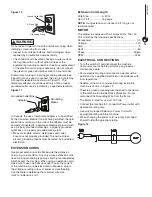
Страница 6: ...d the workbench 4 ASSEMBLY Figure 9 Bolt Workbench Rubber Washer Flat Washer Hex Nut Flat Washer Sander POWER SOURCE WARNING Do not connect to the power source until the machine is completely assembled The machine is wired for 120 volts 60 HZ alternating current Before connecting the machine to the power source make sure the switch is in the OFF position Running the unit on voltages which are not ...

Страница 7: ...ian EXTENSION CORDS Use proper extension cords Make sure the extension cord is in good condition Use only 3 wire extension cords have 3 prong grounding type plugs and 3 pole receptacles which accept the tool plug When using an extension cord make sure to use one heavy enough to carry the current of the machine An undersized cord will cause a drop in the voltage resulting in loss of power and overh...

Страница 8: ... belt conforms to a curved edge for sanding and polishing Remove the backstop See Backstop under Assembly Turn the sander ON and slowly feed it into the sanding belt MAINTENANCE WARNING For your own safety turn the switch OFF and remove the plug from the electrical outlet before adjusting or performing maintenance or lubrication work on the belt sander GENERAL MAINTENANCE Before using check to mak...

Страница 9: ... 2 Inspect all connections on motor for loose or shorted terminals and or worn insulation 3 Install correct fuses or circuit breakers or switch tool to an appropriately size circuit Motor overheats 1 Motor overloaded 2 Extension cord too long and of insufficient gauge weight 1 Reduce load on motor pressure on object being sanded 2 Utilize an extension cord of appropriate gauge and length or plug t...

Страница 10: ...1 x 30 BELT SANDER PARTS ILLUSTRATION 8 PARTS LIST 8 ...

Страница 11: ...30019 Spark Shield 20 BD1030020 Washer Φ4 21 BD1030021 Screw M4X10 22 BD1030022 Spring 23 BD1030023 Washer Φ10 24 BD1030024 Bolt M10X30 Key Part Description Specification 25 BD1030025 Axle Seat 26 BD1030026 Spring Pin Φ3X18 27 BD1030027 Spring 28 BD1030028 Tension Handle 29 BD1030029 Spring 30 BD1030030 Washer Φ5 31 BD1030031 Lock E Ring Φ4 32 BD1030032 Motor Assembly 32 1 BD1030032 1 Motor 1 3HP ...

Страница 12: ...he proof of purchase documentation which includes a date of purchase POWERTEC will either repair or replace any defective part at our option at no charge to you The repaired or replacement unit will be covered by the same limited warranty for the balance of one year warranty period WHAT IS NOT COVERED This warranty applies to the original purchaser at retailer and may not be transferred This warra...

Страница 13: ...NOTE ...

Страница 14: ...NOTE ...

Страница 15: ...NOTE ...

Страница 16: ...Southern Technologies LLC 3816 Hawthron CT Waukegan IL 60087 ...

Отзывы: