


第 4 页 共 16 页
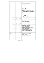
End back tacking
W seam
Sewing segments
index
Multi-seam
Numeric character
display (pin number /
parameter)
Trigger function
Footlifter
after
trimming
Automatic test
Middle stop footlifter
Clamp function
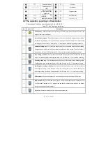
2.2 The operation panel keys of description
A description of each key operation panel shown in Table 2-2.
Table 2-2 : Key Functions instruction
No
Appearance
Description
1
Function key
:
Major operation to determine and confirm working, and work with other key to set
a higher level of the parameter.
2
start back tacking key
:
Every effective press the key once; round with single start back tacking,
double start back tacking, four start back tacking and close start back tacking. The current status
is displayed on the left of LCD.
Detailed see "3.1.2 before and after sewing settings instruction.
3
end back tacking key
:
Every effective press the key once; round with single end back tacking,
double end back tacking, four end back tacking and close end back tacking. The current status is
displayed on the left of LCD. Detailed see "3.1.2 before and after sewing settings instruction.
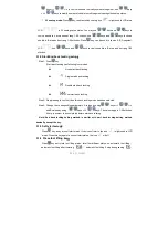
4
Free sewing mode key
:
Every effective pushed the key once; the system selects free sewing
mode. The free sewing status is displayed below LCD.
Detailed see "3.1.1 model sets of sewing."
5
W sewing mode key
:
Every effective pushed the key once; the system selects W sewing mode.
The
W
sewing status is displayed below LCD screen. Detailed see "3.1.1 model sets of sewing."
6
Multi-segment sewing mode key:
Every effective pushed the key once; the system selects
multi-segment sewing mode, pressed
P
key into the number of the needled setting. The
multi-segment sewing status is displayed below LCD. Detailed see "3.1.1 model sets of sewing."
7
Soft start key:
Select soft start function. It will show soft start status on top of LCD screen.
8
Stop position key
:
Select up/down stop position. The up/down stop position is displayed on top
of LCD screen. Detailed see "3.1.7 stop position set. [Note: automatic trimming back, the system
is always on the up of needle position.]
9
Cycle key
:
Switch parameter position when change parameter
;


