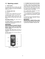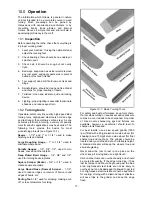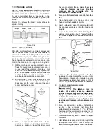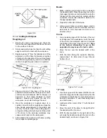
12
Use only 3-wire extension cords that have 3-prong
grounding plugs and 3-pole receptacles that accept
the tool's plug.
Repair or replace damaged or worn cord
immediately.
This tool is for use on a nominal 120-V circuit, and
has a grounded plug that looks like the plug
illustrated in sketch A in Figure 7-1. A temporary
adaptor that looks like the adaptor illustrated in
sketches B and C may be used to connect this plug
to a 2-pole receptacle as shown in sketch B if a
properly grounded outlet is not available.
The temporary adaptor should be used only until a
properly grounded outlet (sketch A) can be installed
by a qualified electrician. The green colored rigid
ear, lug, or the like extending from the adaptor must
be connected to a permanent ground such as a
properly grounded outlet box cover. Whenever the
adaptor is used, it must be held in place by a metal
screw.
In Canada, the use of a temporary adaptor is not
permitted by the Canadian Electrical Code, C22.1.
Figure 7-1: plug configuration
7.2
Extension cords
The use of extension cords is discouraged; try to
position machines near the power source. If an
extension cord is necessary, make sure it is in good
condition. When using an extension cord, be sure to
use one heavy enough to carry the current your
product will draw. An undersized cord will cause a
drop in line voltage resulting in loss of power and
overheating. Table 2 shows correct size to use
depending on cord length and nameplate ampere
rating. If in doubt, use the next heavier gauge. The
smaller the gauge number, the heavier the cord
Amp Rating
Volts Total length of cord in feet
More
Than
Not
More
Than
120 25 50 100 150
AWG
0 6
18
16
16 14
6 10
18
16
14 12
10 12
16
16 14 12
12 16
14
12
Not
Recommended
Extension Cord Recommendations
Table 2
8.0
Adjustments
8.1
Headstock/tailstock movements
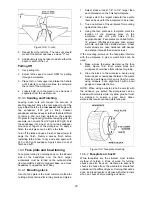
To slide headstock or tailstock, loosen locking
handle (A, Figure 8-1) until head/tailstock can slide
freely. When head/tailstock is positioned, swing
locking handle until it tightens securely.
To remove headstock, tailstock or tool support base
from bed, unscrew and remove stud at either end
(B, Figure 8-1). NOTE: After re-mounting these
items on the Lathe, always insert stud.
Figure 8-1: headstock, tailstock, tool support
Inboard turning:
For most spindle turning operations, the headstock
will be positioned at left end of bed, and only the
tailstock moved to accommodate the workpiece.
Loosen locking handle (C, Figure 8-1) to advance or
retract tailstock quill by rotating handwheel (D).
Retighten handle (C) before operating lathe.
Lock
tailstock in position before operating.
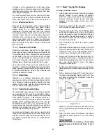
Outboard turning:
For outboard turning, remove tailstock and tool rest
assembly from bed, and slide headstock to opposite
end of bed, as shown in Figure 8-2.
Lock headstock
in position before operating.
Figure 8-2: outboard turning position
Содержание PM2014
Страница 27: ...27 15 1 1 PM2014 Headstock Assembly Exploded View ...
Страница 30: ...30 15 2 1 PM2014 Bed Toolrest and Tailstock Assemblies Exploded View ...
Страница 35: ...35 16 0 Electrical connections PM2014 Lathe cont next page ...
Страница 36: ...36 cont ...
Страница 38: ...38 This page intentionally left blank ...
Страница 39: ...39 This page intentionally left blank ...
Страница 40: ...40 427 New Sanford Road LaVergne Tennessee 37086 Phone 800 274 6848 www powermatic com ...


