14
6. Inspect the cutting edge of the knives for
nicks or wire edge. Hone the knives slightly
using a stone or if the knives are to be
sharpened, maintain a cutting angle of 35
degrees.
7. Insert springs, knife and gib into slot of
cutterhead. Back out screws just enough to
hold the knife in the cutterhead.
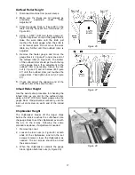
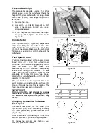
8. Place knife setting gauge (Figure 19) over
knife.
9. While holding down the knife gauge, loosen
all six screws by turning them into the gib
until the cutting edge of the knife comes in
contact with the protrusion of the gauge.
Snug up the gib by slightly backing out the
six screws against the slot.
NOTE: At this time, only tighten the knife
into the slot just enough to hold the knife in
position.
10. Replace and re-set the other three knives in
the same manner.
11. After all four knives are set with the screws
just snug, back out and tighten the six
screws against the slot starting with the end
screws first and then the center screws until
the knife is securely held in the cutterhead.
Tighten the remaining three knives in the
same manner.
After replacing and checking
knives, check again carefully. Make certain
the direction of knives is correct and all 24
gib screws are tightened securely.
Replacing or Rotating Knife Inserts
(Model 209HH only)
The knife inserts on the model 209HH are four-
sided. When dull, simply remove each insert,
rotate it 90° for a fresh edge, and re-install it.
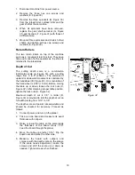
Use the provided screwdriver with the T25P
socket adaptor to remove the knife insert screw.
See Figure 20.
NOTE:
A T25 adaptor or driver
can round out the screw head recess. Always
use a
T25-
Plus
driver or adaptor.
It is advisable to rotate all inserts at the same
time to maintain consistent cutting. However, if
one or more knife inserts develops a nick, rotate
only those inserts that are affected.
Each knife insert has an etched reference mark
so you can keep track of the rotations.
IMPORTANT:
When removing or rotating
inserts, clean saw dust from the screw, the
insert, and the cutterhead platform.
Figure 19 repeated
Figure 20 – Model 209HH only
Dust accumulation between these elements can
prevent the insert from seating properly, and
may affect the quality of the cut.
To install new knife inserts:
1. Before installing each screw, lightly coat the
screw threads with machine oil and wipe off
any excess.
2. Position knife insert and move it back and
forth to verify there are no burrs or dirt.
3. Hold insert away from the back of the seat
(pull slightly toward yourself if facing the
cutting edge) and allow the screw to pull
insert into position. Note: A slight offset
between screw hole and hole in knife insert
is normal. Do not position insert directly over
screw hole, as it could ride up on the back of
the seat and potentially cause cracking of
the tip.
4. Securely tighten each screw which holds the
knife inserts before operating the planer.
IMPORTANT:
Maximum torque for
tightening the screws is 45 to 55 inch
pounds (3.75 to 4.6 foot pounds).
Содержание 209-1
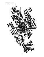
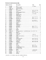
Страница 25: ...25 Cutterhead Assembly ...
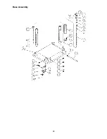
Страница 28: ...28 Base Assembly ...
Страница 30: ...30 Gearbox Assembly ...
Страница 35: ...35 Electrical Connections Single Phase 230 Volt only ...
Страница 39: ...39 ...
Страница 40: ...40 427 New Sanford Rd LaVergne TN 37086 Phone 800 274 6848 www powermatic com ...
Страница 65: ...25 Dispositif de la tête de la découpeuse ...
Страница 68: ...28 Montage de la base ...
Страница 70: ...30 Dispositif de la boîte de vitesses ...
Страница 75: ...35 Connexions électriques phase unique 230 volts uniquement ...
Страница 79: ...39 ...
Страница 80: ...40 427 New Sanford Rd LaVergne TN 37086 Téléphone 800 274 6848 www powermatic com ...
Страница 105: ...25 Conjunto de Cabeza de Corte ...
Страница 108: ...28 Conjunto de Base ...
Страница 110: ...30 Conjunto de la Caja de Velocidades ...
Страница 115: ...35 Conexiones Eléctricas Monofásico 230 Voltios solamente ...
Страница 119: ...39 ...
Страница 120: ...40 427 New Sanford Rd LaVergne TN 37086 Teléf 800 274 6848 www powermatic com ...


