11
Extension Cords
The use of an extension cord is not
recommended for this machine, but if one
proves necessary make sure the cord rating is
suitable for the amperage listed on the
machine's motor plate. An undersized cord will
cause a drop in line voltage resulting in loss of
power and overheating.
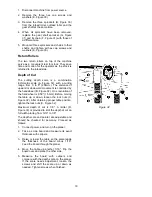
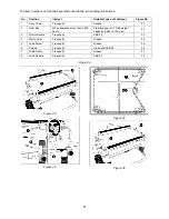
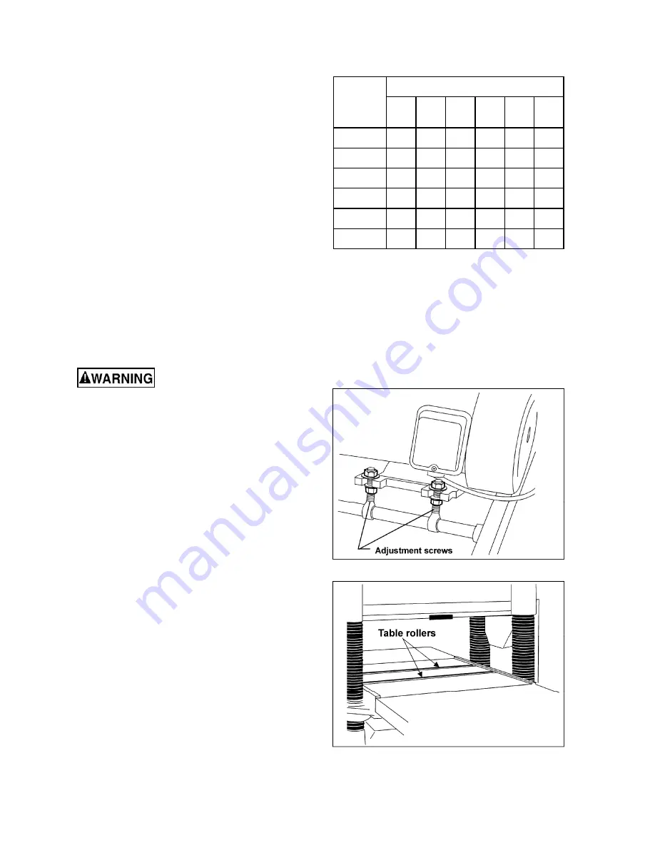
The chart in Figure 11 shows the correct size
cord to use based on cord length and motor
plate amp rating. If in doubt, use the next
heavier gauge. The smaller the gauge number
the heavier the cord.
Adjustments
Tools required for adjustments:
3, 5, 6, and 10mm hex wrenches
12, 14 and 19mm open-end wrenches
Feeler gauges
Straight edge
Gauge block or dial gauge
Cross-point (Phillips) screwdriver
Disconnect machine from
power source before making any adjust-
ments (except feed rate).
Belt Tension
Inspect the tension of the belts frequently during
the first few times you use the planer. Belts often
stretch during this trial period. If they require
tightening, proceed as follows:
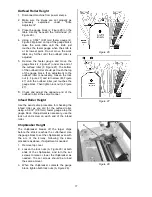
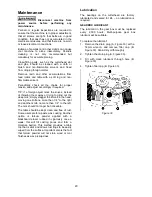
1. Remove the belt guard and the rear panel.
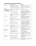
2. Loosen the bottom nuts on the motor
adjustment screws (Figure 12) with a 19mm
wrench.
3. Turn the top nuts to lower the motor plate,
which will increase the belt tension.
4. Proper tension is achieved when there is
slight deflection in the belt midway between
the pulleys, using moderate finger pressure.
5. Tighten the bottom nuts (Figure 12).
Table Rollers
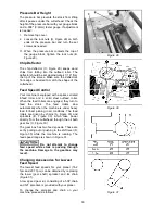
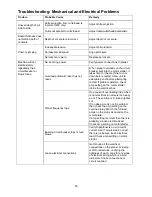
Your planer is supplied with two table rollers
(Figure 13) which turn as the stock is fed into the
machine, thus reducing friction. It is not possible
to give exact dimensions on the proper height
setting of the table rollers because each type of
wood behaves differently. As a general rule,
however, when planing rough stock the table
rollers should be set at high position.
Recommended Gauges (AWG) of Extension Cords
Amps
Extension Cord Length *
25
feet
50
feet
75
feet
100
feet
150
feet
200
feet
<
5
16 16 16 14 12 12
5
to
8 16 16 14 12 10 NR
8 to 12
14
14
12
10
NR
NR
12
to
15 12 12 10 10 NR NR
15
to
20 10 10 10 NR NR NR
21
to
30 10 NR NR NR NR NR
*based on limiting the line voltage drop to 5V at 150% of the
rated amperes.
NR: Not Recommended.
Figure 11
Figure 12
Figure 13
Содержание 209-1
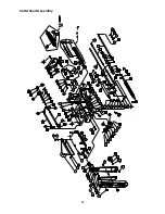
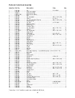
Страница 25: ...25 Cutterhead Assembly ...
Страница 28: ...28 Base Assembly ...
Страница 30: ...30 Gearbox Assembly ...
Страница 35: ...35 Electrical Connections Single Phase 230 Volt only ...
Страница 39: ...39 ...
Страница 40: ...40 427 New Sanford Rd LaVergne TN 37086 Phone 800 274 6848 www powermatic com ...
Страница 65: ...25 Dispositif de la tête de la découpeuse ...
Страница 68: ...28 Montage de la base ...
Страница 70: ...30 Dispositif de la boîte de vitesses ...
Страница 75: ...35 Connexions électriques phase unique 230 volts uniquement ...
Страница 79: ...39 ...
Страница 80: ...40 427 New Sanford Rd LaVergne TN 37086 Téléphone 800 274 6848 www powermatic com ...
Страница 105: ...25 Conjunto de Cabeza de Corte ...
Страница 108: ...28 Conjunto de Base ...
Страница 110: ...30 Conjunto de la Caja de Velocidades ...
Страница 115: ...35 Conexiones Eléctricas Monofásico 230 Voltios solamente ...
Страница 119: ...39 ...
Страница 120: ...40 427 New Sanford Rd LaVergne TN 37086 Teléf 800 274 6848 www powermatic com ...


